
A kind of automatic incision equipment and incision method

A cutting and automatic technology, applied in the direction of metal processing, etc., can solve the problems of no disclosure, low degree of automation, burrs at the cutting, etc.

Active Publication Date: 2019-04-23
BEIJING TIANMA INTELLIGENT CONTROL TECH CO LTD +1
View PDF7 Cites 0 Cited by
  • Summary
  • Abstract
  • Description
  • Claims
  • Application Information

AI Technical Summary

Problems solved by technology

In many cases, due to the poor control of the incision angle, some incision angles exceed the allowable range, resulting in defective products. In addition, the cutting edge of the cutter will become blunt after a long time, and the cutting speed will vary, which will also cause The generation of burrs at the incision is not allowed by the quality
[0003] The traditional way of incision is artificial incision. Its limitation is low efficiency. Workers can complete a workpiece in 2 to 3 seconds, which can reach 1200 to 1500 pieces per hour. After that, the work efficiency gradually decreases and cannot complete 1000 pieces per hour. On average, it is about 5,000 per day; secondly, the quality is unreliable. When manual incision is made, the angle of the cutter is completely controlled by the hand. The angle of each incision must be different, the shape is different, and there is no consistency. Due to the poor control of the incision angle , the angle of some cuts exceeds the allowable range, resulting in defective products, such as image 3 shown
[0004] CN204123436U discloses a kind of oblique cutting mechanism for plastic rings, which can realize mechanical automation, but it does not disclose other parts other than the cutting mechanism, the degree of automation is low, and it is impossible to greatly improve the cutting efficiency

Method used


Image

  • A kind of automatic incision equipment and incision method
  • A kind of automatic incision equipment and incision method
  • A kind of automatic incision equipment and incision method

Examples


Embodiment Construction

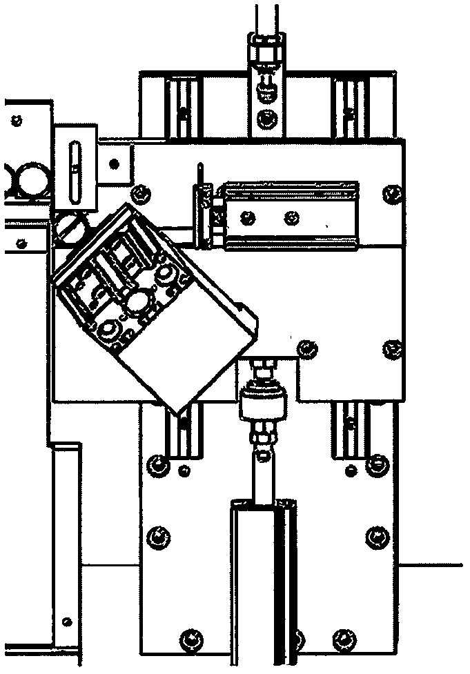
[0037] In this embodiment, the ring cutout is taken as an example to illustrate its structure and cutout method.

[0038] The present invention will be further described in detail below in conjunction with the accompanying drawings and embodiments, but not as any limitation of the present invention.

[0039] The present invention is an automatic cutting device, which is composed of a vibrating feeding part 1, a vibrating straight rail 2, a cutting part 3, a blanking chute 4, a finished product collecting part 5, and an equipment stand 6. The specific structure is as follows Figure 5 shown. Including a vibrating feeding part 1, a vibrating straight track 2, a notch part 3, a blanking chute 4, a finished product collecting part 5, and an equipment stand 6, the vibrating feeding part 1, the vibrating straight track 2 and the notch part 3 are sequentially Set on the table top of the equipment stand 6, the blanking chute 4 is set on one side of the cutout part 3 and below the vib...


PUM

PropertyMeasurementUnit
Thicknessaaaaaaaaaa
Diameteraaaaaaaaaa

Abstract

The invention discloses automatic cutting equipment and method. The cutting equipment is used for cutting a ring-shaped object, and consists of a vibrating and feeding part, a vibrating straight rail,a cutting part, a dropping slot, a finished product collecting part, an equipment stand and the like. The method comprises the following steps of: loading by the vibrating and feeding part, feeding by the vibrating straight rail, introducing the ring-shaped object into the cutting part, separating materials up and down, cutting the ring-shaped object, discharging the ring-shaped object and risingthe cutting part. The cutting equipment and method disclosed by the invention solves the technical problems that a conventional manual cutting method is inconsistent in angle and is not smooth, and adopts an automatic way; and a cutter is driven by the air cylinder, so that the position and the angle are fixed; and acting speed of the air cylinder is adjustable, so that the cutting angle of the ring-shaped object is strictly consistent under conditions of the fixed position and high speed, and the cut ring-shaped object is smooth and is free of burrs.

Description

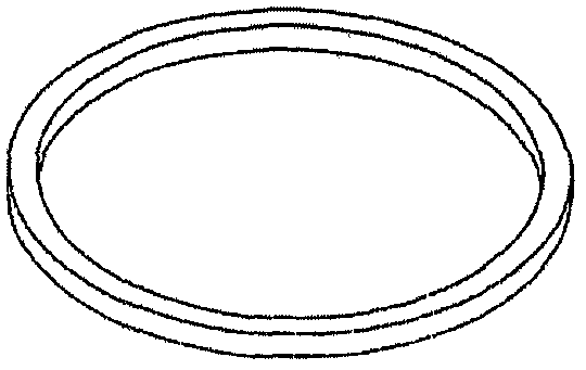
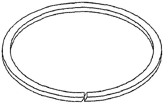
technical field [0001] The invention relates to an automatic cutting device and a cutting method, which are used for cutting a neat and smooth knife edge on a ring. Background technique [0002] The ring is a circular ring product widely used in hydraulic and pneumatic systems, such as retaining rings, such as figure 1 shown. It is mainly assembled in the oil cylinder, air cylinder and solenoid valve body, the purpose is to protect the rubber sealing ring from wear and tear, thereby prolonging the service life of the product. The main material of the retaining ring is polytetrafluoroethylene and polyoxymethylene, etc., which have low elasticity, strong wear resistance, and certain rigidity. Because of its lack of elasticity, it cannot be installed by elasticity like a rubber sealing ring during assembly. in the trench. The retaining ring must be cut obliquely before use, and the cut angle is generally 45±15 degrees, such as figure 2 shown. In many cases, due to the poo...

Claims


Application Information

Patent Timeline
IPC IPC(8): B23D79/00B23Q7/00
CPCB23D79/00B23Q7/00
Inventor 董军科苑士泽熊玮谢赛陈岩霞张革玉
Owner BEIJING TIANMA INTELLIGENT CONTROL TECH CO LTD
Learn More