
Mesh correction ejection mechanism

A technology of ejection mechanism and mesh cloth, which is applied in the direction of coating, etc., can solve the problems of difficult debugging and replacement, high processing cost, and prolonged feeding cycle, so as to improve equipment utilization rate, improve production efficiency, and reduce maintenance time Effect

Active Publication Date: 2017-04-26
GOERTEK INC
View PDF6 Cites 0 Cited by
  • Summary
  • Abstract
  • Description
  • Claims
  • Application Information

AI Technical Summary

Problems solved by technology

In the first method, the structure of the correction jaw is complex, the processing cost is high, the lowering height is very limited, and it is easy to be broken or stuck. Once it is broken or stuck, it is very difficult to replace; in the second method, the lowering action is added to lengthen the feeding cycle. And it is difficult to debug and replace

Method used


Image

  • Mesh correction ejection mechanism
  • Mesh correction ejection mechanism
  • Mesh correction ejection mechanism

Examples


Embodiment Construction

[0025] In order to make the object, technical solution and advantages of the present invention clearer, the present invention will be further described in detail below in conjunction with the accompanying drawings and embodiments. It should be understood that the specific embodiments described here are only used to explain the present invention, not to limit the present invention.

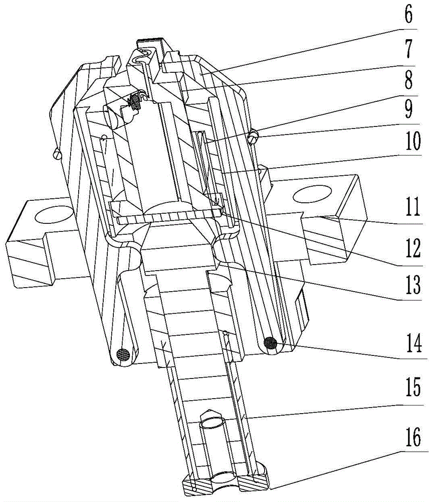
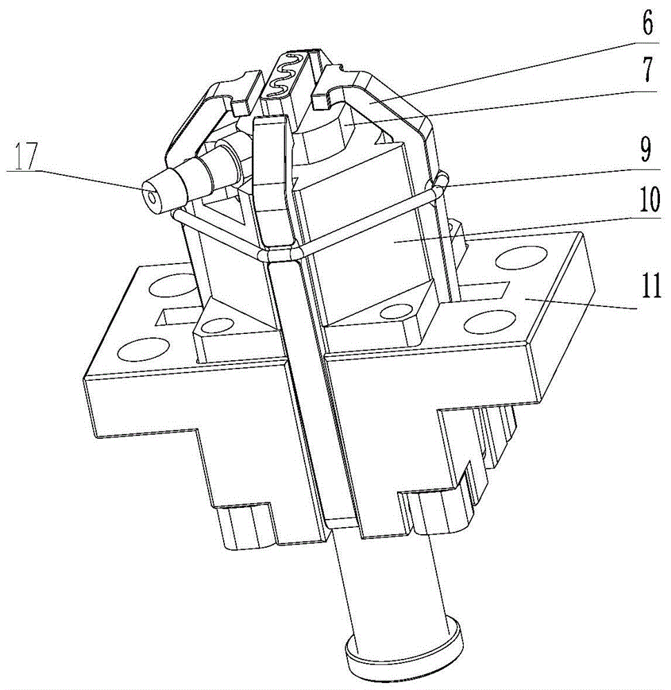
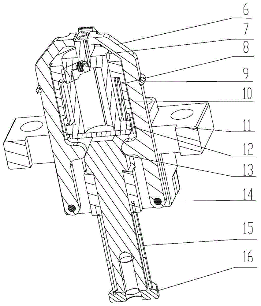
[0026] Such as Figure 1-2 As shown, a mesh correction and ejection mechanism provided by the present invention includes a correction jaw 6, a mesh suction head 7, a suction head sliding sleeve 10, a fixing seat 11 and a push rod 13, wherein the suction head sliding sleeve 10 is fixedly installed On the fixed seat 11, the mesh suction head 7 is inserted in the suction head sliding sleeve 10 and can move in the axial direction. A coaxial central through hole, the push rod 13 is inserted in the central through hole and abuts against the mesh suction head 7 . The outer side of the suction head slidi...


PUM


Abstract

The invention belongs to the technical field of material locating, and particularly relates to a correction and ejection mechanism for screen cloth. The correction and ejection mechanism comprises correction clamping jaws, a screen cloth suction head, a suction head sliding sleeve, a fixed seat and an ejector rod. The suction head sliding sleeve is fixedly arranged on the fixed seat. The screen cloth suction head is inserted in the suction head sliding sleeve and can move in the axial direction. A center through hole coaxial with the suction head sliding sleeve is formed in the fixed seat. The ejector rod is inserted in the center through hole and abuts against the screen cloth suction head. The correction clamping jaws hinged to the fixed seat are arranged on the outer side of the suction head sliding sleeve in the circumferential direction. Protruding structures in contact with the ejector rod are arranged on the inner sides of the correction clamping jaws. The ejector rod can move in the axial direction under the action of external force, and therefore the correction clamping jaws are opened or closed, and the screen cloth suction head is ejected or retracted. The screen cloth is sucked, corrected and located synchronously, and is ejected after being located. The correction and ejection mechanism is in the structure of an independent system, local fast replacement can be achieved, and mounting and adjusting are convenient.

Description

technical field [0001] The invention belongs to the technical field of material positioning, in particular to a mesh correction and ejection mechanism. Background technique [0002] In electro-acoustic components, in order to ensure the input and output of sound, and at the same time based on the demand for dust prevention, mesh cloth is usually added to the injection molded parts to solve the problem. Mesh can be attached to the surface of the workpiece with an adhesive after the injection molding is formed, or it can be integrally formed by precise positioning and feeding during the injection molding process; but the former increases the process, the cost is high, and the adhesion is not strong, and the quality is uneven. Therefore, the mesh cloth of most electro-acoustic products generally adopts the method of fine positioning and feeding of the mesh cloth and integral injection molding with the workpiece. [0003] The mesh automatic feeding machine needs to transfer the...

Claims


Application Information

Patent Timeline
Patent Type & Authority Patents(China)
IPC IPC(8): B29C45/14B29C45/17
CPCB29C45/14B29C2045/14868
Inventor 宋宾冯震王进强尹光远谭政张烨
Owner GOERTEK INC
Learn More