
Flange plate drilling equipment

A technology of drilling equipment and flanges, which is applied in the direction of drilling/drilling equipment, boring/drilling, metal processing equipment, etc., and can solve the problems of low production efficiency, low drilling accuracy, waste of manpower and material resources, etc. , to achieve the effect of strong practicability and simple structure

Inactive Publication Date: 2018-05-08
饶琼珊
View PDF0 Cites 5 Cited by
  • Summary
  • Abstract
  • Description
  • Claims
  • Application Information

AI Technical Summary

Problems solved by technology

[0002] In our modern life, flanges are relatively common, especially in the field of machinery, which is quite extensive. Flanges are important parts for connecting various pipes and valves, usually connected to pipe ends, for two There are certain requirements for the position of the bolt holes when the flange is matched. Now the more commonly used drilling method is to use drilling equipment to complete. For pipes with different diameters, the number, diameter, and center of the flange holes The distance is also different, and special fixtures are often made according to their different needs, and the existing drilling equipment has low drilling accuracy, complex structure, waste of manpower and material resources, increased production costs, and low production efficiency

Method used


Image

  • Flange plate drilling equipment
  • Flange plate drilling equipment
  • Flange plate drilling equipment

Examples


Embodiment Construction

[0024] Below in conjunction with accompanying drawing and embodiment of description, specific embodiment of the present invention is described in further detail:

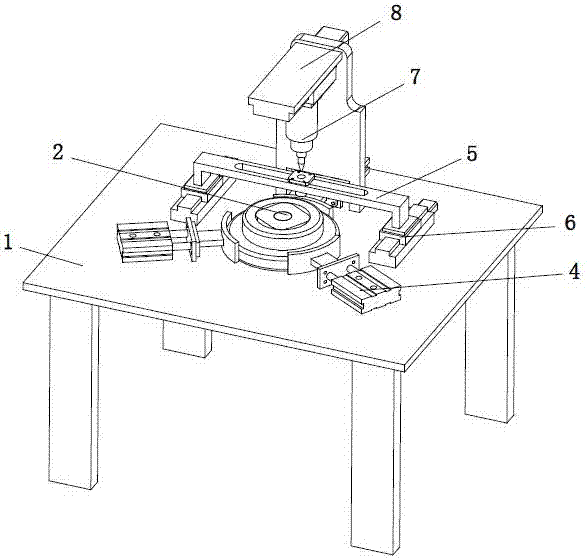
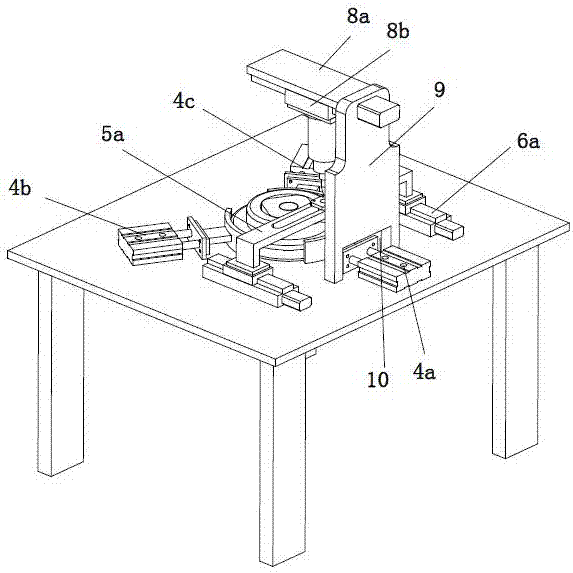
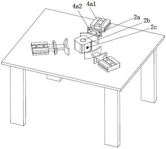
[0025] refer to Figure 1 to Figure 9 The shown drilling equipment for a flange includes a workbench 1, the top center of the workbench 1 is provided with a limit assembly 2 for limiting flanges with different inner diameters, and the limit assembly 2 The bottom of the workbench 1 is provided with a first driving mechanism 3 to drive its rotation, and the top of the workbench 1 is provided with a positioning mechanism 4 for positioning the flange clamp. The positioning mechanism 4 includes three axes along the axis of the adjustment assembly 5 The first positioning assembly 4a, the second positioning assembly 4b and the third positioning assembly 4c are distributed with equiangular differences. The top of the first positioning assembly 4a is provided with a U-shaped and opening downwards for raising the flange drill...


PUM


Abstract

The invention relates to the field of flange plate machining, in particular to flange plate drilling equipment. The flange plate drilling equipment comprises a workbench. A limiting assembly is arranged in the center of the top of the workbench. A first driving mechanism is arranged at the bottom of the limiting assembly. A positioning mechanism is arranged at the top of the workbench and comprises a first positioning assembly, a second positioning assembly and a third positioning assembly which are distributed along the axis of an adjusting assembly with equal angle differences. The adjustingassembly is arranged above the first positioning assembly. A second driving mechanism is arranged at the bottom of the adjusting assembly. A drilling device is arranged above the adjusting assembly.A third driving mechanism is arranged at the top of the drilling device. A supporting plate is arranged at the top of the workbench. A receding notch is formed in the bottom of the supporting plate. The flange plate drilling equipment is simple in structure and can be applicable to the positioning procedure and the drilling procedure of flange plates with difference inner diameters, drill bits anddrill hole die sleeves can be replaced rapidly, the demands for difference drilling diameters of the flange plates are met, and the practicability is higher.

Description

technical field [0001] The invention relates to the field of flange processing, in particular to a flange drilling device. Background technique [0002] In our modern life, flanges are relatively common, especially in the field of machinery, which is quite extensive. Flanges are important parts for connecting various pipes and valves, usually connected to pipe ends, for two There are certain requirements for the position of the bolt holes when the flange is matched. Now the more commonly used drilling method is to use drilling equipment to complete. For pipes with different diameters, the number, diameter, and center of the flange holes The distance is also different, and its special fixtures are often made according to its different needs, and the existing drilling equipment has low drilling accuracy, complex structure, waste of manpower and material resources, increased production costs, and low production efficiency. Contents of the invention [0003] The object of the...

Claims


Application Information

Patent Timeline
Patent Type & Authority Applications(China)
IPC IPC(8): B23Q1/30B23Q1/64B23B47/28B23B39/00
CPCB23Q1/30B23B39/00B23B47/28B23Q1/64
Inventor 饶琼珊
Owner 饶琼珊
Learn More