
Magnetic separation mechanism and using method thereof

A magnetic separation and magnetic technology, applied in used abrasive processing devices, abrasives, metal processing equipment, etc., can solve problems such as affecting the accuracy of flow control valves, inability to meet equipment, and unstable shot peening (sand) results. Achieve excellent application prospects and market value, simple structure, and avoid instability

Pending Publication Date: 2018-05-08
昆山开信精工机械股份有限公司
View PDF8 Cites 0 Cited by
  • Summary
  • Abstract
  • Description
  • Claims
  • Application Information

AI Technical Summary

Problems solved by technology

Internationally, shot peening (sand) processing equipment was used earlier and more commonly in some developed countries such as Europe and the United States, and their shot peening (sand) strengthening technology and equipment are also relatively mature, but these equipment also face the same problem: in conventional use In the processing technology of non-magnetic material shot peening (sand), it is often because various magnetic substances are gradually mixed in during the shot material circulation process, which affects the accuracy of the flow control valve and further makes the shot peening (sand) result unstable.
However, this control method can no longer meet the requirements of high efficiency and automation required by today's society for equipment.

Method used


Image

  • Magnetic separation mechanism and using method thereof
  • Magnetic separation mechanism and using method thereof
  • Magnetic separation mechanism and using method thereof

Examples


Embodiment Construction

[0028] The present invention will be described in further detail below in conjunction with the accompanying drawings.

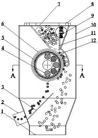
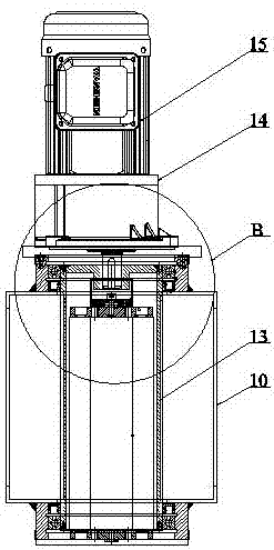
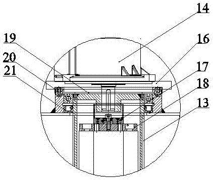
[0029] refer to Figure 1 to Figure 6 , a magnetic separation mechanism, including a magnetic separation chamber 10, a rotor separation assembly 6 disposed in the magnetic separation chamber 10, and a drive assembly for driving the rotor separation assembly 6 to rotate, and the rotor separation assembly 6 utilizes its internal design The magnetism of some magnetic adsorption components 5 absorbs and separates the magnetic substances entering the tiles in the magnetic separation chamber 10 during the rotation process.

[0030] A V-shaped hopper 7 is arranged inside the inlet of the magnetic separation chamber 10 , and the outlet of the V-shaped hopper 7 is close to the rotor separation assembly 6 and located above the magnetic side of the rotor separation assembly 6 .

[0031] The discharge port of the V-shaped hopper 7 is provided with an arc-shaped deflecto...


PUM


Abstract

The invention relates to the technical field of shot (sand) blasting machining, in particular to a magnetic separation mechanism and a using method thereof. The magnetic separation mechanism comprisesa magnetic separation cavity, a rotor separation assembly arranged in the magnetic separation cavity and a driving assembly used for driving the rotor separation assembly to rotate. Magnetic substances in shot entering the magnetic separation cavity are attracted and separated out in the rotating process by utilizing magnetism of a magnetic attraction assembly arranged in the rotor separation assembly. According to the magnetic separation mechanism, magnetic separation of the circulation shot can be achieved in the equipment shot (sand) blasting process, separation operation can be conductedwithout the need of waiting for shutting-down of the magnetic separation mechanism, and the shot (sand) blasting working efficiency is higher; and the structure is simple, operation is convenient, theautomated degree is high, the practicability is high, maintenance and repairing are convenient, particularly the magnetic separation mechanism is more suitable for operation of large parts and large-batch and long-time shot (sand) blasting, and the magnetic separation mechanism has an excellent application prospect and excellent market value.

Description

technical field [0001] The invention relates to the technical field of shot peening (sand) processing, in particular to a magnetic separation mechanism and its application method. Background technique [0002] Shot peening (sand) treatment has been used for decades as a processing technology to improve the fatigue strength of metal parts and improve the mechanical properties of the workpiece surface. Due to the complex process of shot peening (sand) processing and the high degree of automation required, the processing equipment is a high-tech system integrating information technology, electronic technology, automation technology and manufacturing technology. Internationally, shot peening (sand) processing equipment was used earlier and more commonly in some developed countries such as Europe and the United States, and their shot peening (sand) strengthening technology and equipment are also relatively mature, but these equipment also face the same problem: in conventional us...

Claims


Application Information

Patent Timeline
Patent Type & Authority Applications(China)
IPC IPC(8): B24C9/00
CPCB24C9/006
Inventor 张丽君周阳赵银辉周瑞玺陈小虎
Owner 昆山开信精工机械股份有限公司
Learn More