Novel rapid mounting pneumatic vibrator

A pneumatic vibrator, fast technology, applied in the direction of vibrating fluid, ceramic molding machine, manufacturing tools, etc., can solve the problems of short service life, troublesome installation, small vibration force, etc., to reduce product weight, fast and convenient installation , Improve the effect of exciting force

Pending Publication Date: 2018-05-08
WOLONG ELECTRIC GRP CO LTD +1
View PDF0 Cites 1 Cited by
  • Summary
  • Abstract
  • Description
  • Claims
  • Application Information

AI Technical Summary

Problems solved by technology

[0003] At present, most pneumatic vibrators have problems such as troublesome installation, large air consumption, small exciting force, short service life and easy damage.

Method used


Image

  • Novel rapid mounting pneumatic vibrator
  • Novel rapid mounting pneumatic vibrator
  • Novel rapid mounting pneumatic vibrator

Examples


Embodiment Construction

[0037] The technical solution of the present invention will be further described in detail below in conjunction with the accompanying drawings.

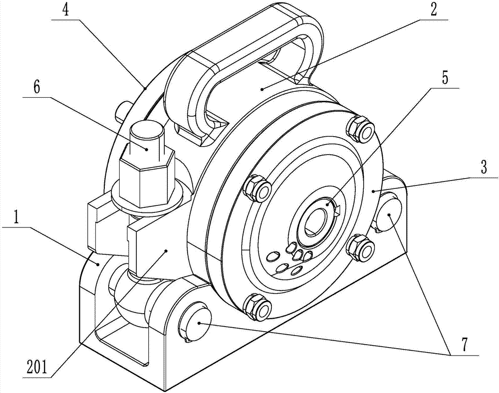
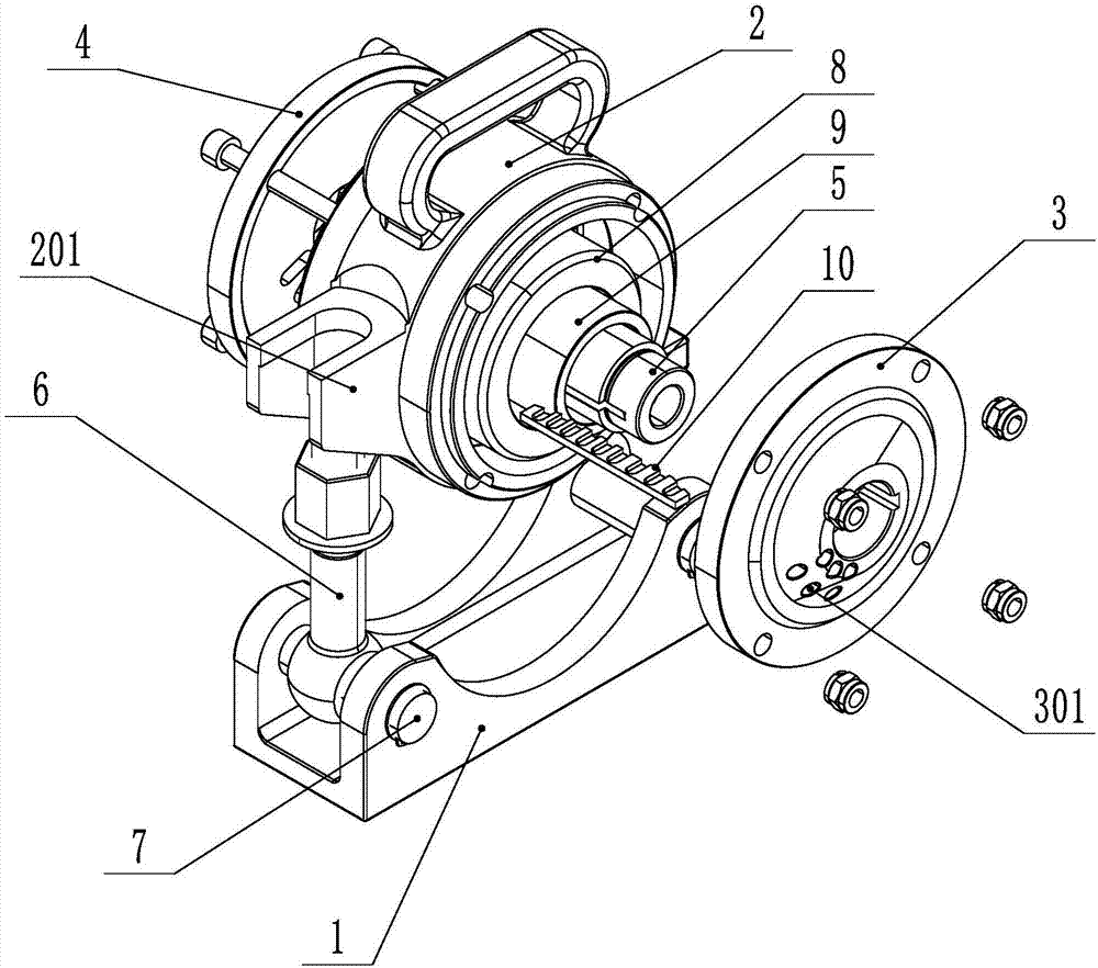
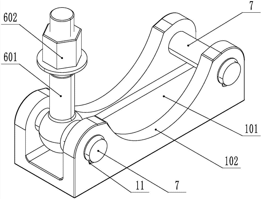
[0038] Such as Figure 1-8 As shown, a new type of quick-installation pneumatic vibrator includes a base 1 connected to the mold, a machine base 2 arranged on the base 1, a front end cover 3 and a rear end cover 4 respectively arranged on the front and rear sides of the machine base 2, The front and rear ends are connected with the front end cover 3 and the rear end cover 4 respectively, the central axis 5, the eccentric rotation inner casing 9 arranged outside the central axis 5, the eccentric rotation outer casing arranged between the eccentric rotation inner casing 9 and the machine base 2 Pipe 8, central shaft 5 center and outer side are provided with air chamber 501 and chute 503 respectively, central shaft 5 is located on the side of front end cover 3 and is provided with the connection port 504 that air chamber 501 is connecte...


PUM

PropertyMeasurementUnit
hardnessaaaaaaaaaa

Abstract

The invention discloses a novel rapid mounting pneumatic vibrator, and relates to the field of pneumatic vibrators. At present, most pneumatic vibrators are trouble to mount, large in gas consumptionamount, small in exciting force, short in service life, easy to damage and the like. The pneumatic vibrator comprises a base, a machine base, a front end cover, a rear end cover, a middle shaft, an eccentric rotating inner casing pipe and an eccentric rotating outer casing pipe; an air chamber and a sliding groove are formed in the center and the outer side of the middle shaft, the side, located on the front end cover, of the middle shaft is provided with a connection port for connecting the air chamber and an air source, a side air outlet is formed in the air chamber and leads to the slidinggroove, a sliding plate capable of closing and opening the air outlet of the air chamber is arranged in the sliding groove, a rapid mounting structure is arranged between the machine base and the baseand can be detachably connected, the rapid mounting structure comprises a rapid positioning structure and a bolt type rapid fixing mechanism capable of turning over, and the bolt type rapid fixing mechanism can be rotatably connected to the base. According to the pneumatic vibrator, the gas consumption amount can be effectively reduced, the exciting force is improved, and starting and exhaust effect of the vibrator can be better ensured.

Description

technical field [0001] The invention relates to the field of pneumatic vibrators, in particular to a novel quick-installation pneumatic vibrator. Background technique [0002] Pneumatic vibrators use compressed air as the power source and are widely used in food, medicine, chemical, pesticide, feed, ceramics, glass, cement, fuel and other powder processing industries. For example, in the process of concrete construction, the air source makes the pneumatic vibrator vibrate, and the vibration force is transmitted to the mold through the quick-installation base, so that the voids inside the concrete are filled with mortar, and the air bubbles are squeezed out, thereby achieving a compact effect. [0003] At present, most pneumatic vibrators have problems such as troublesome installation, large air consumption, small excitation force, short service life and easy damage. Contents of the invention [0004] The technical problem to be solved and the technical task proposed by th...

Claims


Application Information

Patent Timeline
Patent Type & Authority Applications(China)
IPC IPC(8): B28B1/087B06B1/18
CPCB28B1/0873B06B1/18
Inventor 卢鹏飞孙鑫周军杜海军
Owner WOLONG ELECTRIC GRP CO LTD
Why Eureka
Try Eureka