
3D printing device for rope traction parallel mechanism

A technology of 3D printing and printing devices, applied in the direction of processing drive devices, additive processing, etc., to achieve the effects of wide practicability, easy disassembly and assembly, and low price

Active Publication Date: 2020-07-14
HEFEI UNIV OF TECH
View PDF6 Cites 0 Cited by
  • Summary
  • Abstract
  • Description
  • Claims
  • Application Information

AI Technical Summary

Problems solved by technology

However, due to the limitation of ordinary rigid structure, length and quality, there is currently no 3D printer that uses a rope traction parallel mechanism to control the 3D printer nozzle to achieve large-scale printing.

Method used


Image

  • 3D printing device for rope traction parallel mechanism
  • 3D printing device for rope traction parallel mechanism
  • 3D printing device for rope traction parallel mechanism

Examples


Embodiment Construction

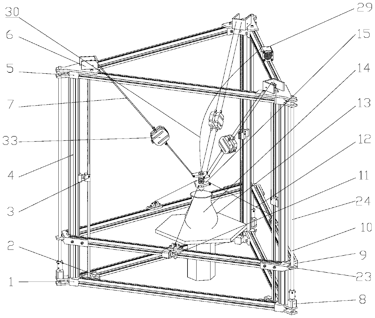
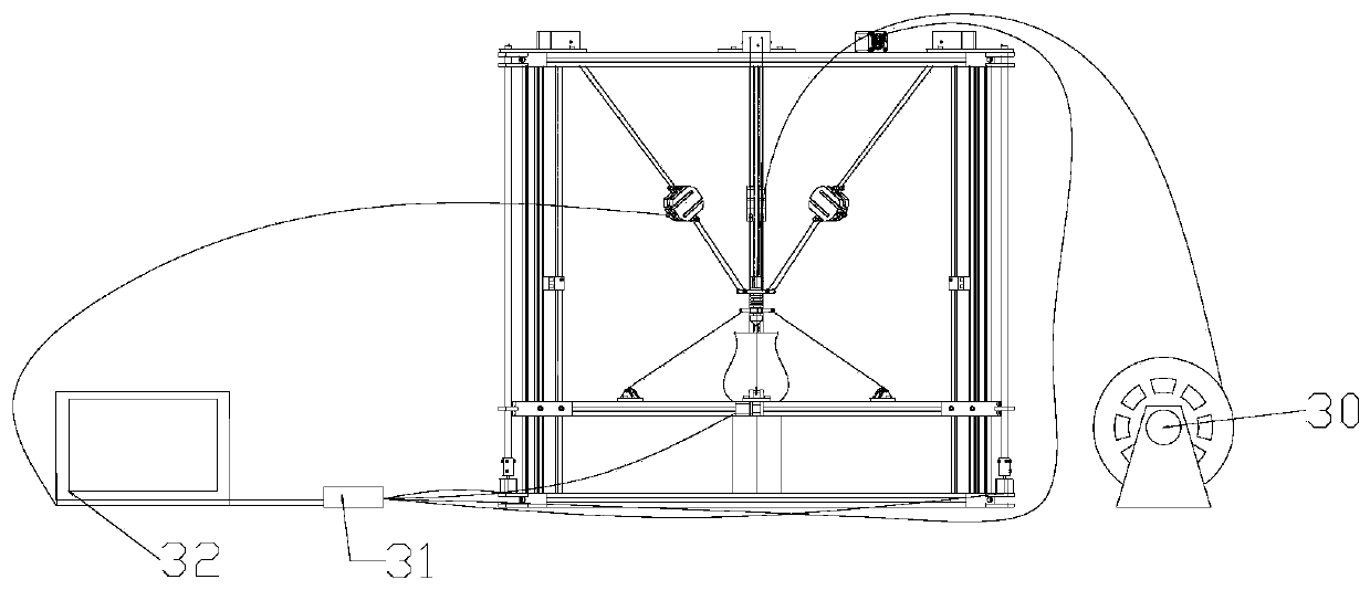
[0021] Such as Figure 1-Figure 6 As shown, the rope traction parallel mechanism 3D printing device includes a bracket, a traction mechanism, an auxiliary adjustment mechanism, and a consumable motor 29, wherein:

[0022] The support includes a lower support frame 1 of an equilateral triangle, and an upper beam frame 5 of the same equilateral triangle is arranged above the lower support frame 1, and a vertical support rod 4 is vertically connected between the triangular positions of the lower support frame 1 and the upper beam frame 5 respectively. , a printing device 15 is provided in the space surrounded by the lower support frame 1, the upper beam frame 5, and the vertical support rod 4;

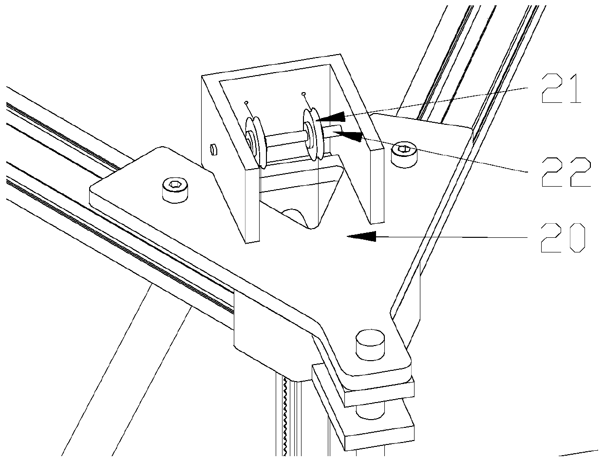
[0023] The traction mechanism includes a conveyor belt motor 2 installed near the lower end of each vertical support bar 4, a guide pulley mechanism 6 installed near the upper end of each vertical support bar 4, a Pulley transmission mechanism 3, pulley transmission mechanism 3 comprises...


PUM


Abstract

The invention discloses a 3D print device adopting a rope traction parallel mechanism. The 3D print device adopting the rope traction parallel mechanism comprises a support, a traction mechanism, an auxiliary adjusting mechanism and a consumable motor. The support is composed of a lower supporting frame, an upper cross beam frame and vertical type supporting rods. A print device is arranged in thesupport. The traction mechanism comprises conveyer belt motors, guide pulley mechanisms and belt pulley transmission mechanisms. According to the traction mechanism, traction flexible ropes are connected to the edge of the upper end of the print device. The auxiliary adjusting mechanism comprises a middle cross beam support, lead screw transmission mechanisms and three winding mechanisms. According to the auxiliary adjusting mechanism, auxiliary flexible ropes are connected to the edge of the lower end of the print device. The consumable motor is installed on one triangular edge of the uppercross beam frame. According to the 3D print device adopting the rope traction parallel mechanism, by the adoption of the parallel drive mechanism combining the traction flexible ropes and the auxiliary flexible ropes, the advantages of high efficiency and high bearing capacity of the print mechanism and the advantages of flexibility and adjustability of a servo drive mechanism are compatible, andthe defects that a traditional machine lacks flexibility and a rigid mechanism cannot be applied in a large space are overcome.

Description

technical field [0001] The invention relates to the field of 3D printing devices, in particular to a 3D printing device of a rope traction parallel mechanism. Background technique [0002] The rope traction parallel mechanism refers to the parallel mechanism that uses ropes instead of traditional connecting rods as traction elements. In recent years, with the continuous development of 3D printing technology, this also puts forward higher requirements for 3D printing, not only requiring high It operates efficiently, and requires a larger output space, which can quickly and conveniently change the size of the 3D printer. However, due to the limitations of ordinary rigid structure, length and quality, there is currently no 3D printer that uses a rope-drawn parallel mechanism to control the 3D printer nozzle to achieve large-scale printing. Contents of the invention [0003] The object of the present invention is to solve the problems existing in the prior art, and provide a ...

Claims


Application Information

Patent Timeline
Patent Type & Authority Patents(China)
IPC IPC(8): B29C64/20B29C64/227B33Y30/00
CPCB29C67/00B33Y30/00
Inventor 钱森张科訾斌王道明王正雨王加攀
Owner HEFEI UNIV OF TECH
Learn More