Full-automatic continuous conveyance mechanism with automatic tightly-pressing device

A technology of pressing device and conveying mechanism, which is applied in the direction of conveyor objects, transportation and packaging, etc. It can solve the problems of increasing intermediate processes, damaging the product surface, and inconvenient operation, so as to reduce work intensity, stabilize conveying frequency, and facilitate work personnel effect

Inactive Publication Date: 2018-05-08
中山市榄商置业发展有限公司
View PDF5 Cites 7 Cited by
  • Summary
  • Abstract
  • Description
  • Claims
  • Application Information

AI Technical Summary

Problems solved by technology

[0002] At present, in the manufacturing industry, the products produced from special equipment are generally designed to be discharged from the slideway. For the situation where there is a high drop (usually higher than 600mm) and a large span between the processes, a large-angle long slideway will be used. The process will A large impact will damage the product surface, so products with high surface requirements cannot adopt this large-angle long slideway design. The common practice is to increase the intermediate process to realize the turnover of the product. For example, the patent application number 201520753985.5, Including the control cabinet; the driving mechanism and the conveying mechanism arranged on the top of the control cabinet. In this patent, the machine cannot automatically carry out the operation of loading materials one by one after the staff fills, and the staff needs to manually push the raw materials to be processed one by one for loading. Operation, it is extremely inconvenient for the staff to operate, which greatly increases the work intensity of the staff. At the same time, during the loading operation, it is impossible to ensure that the raw materials that need to be processed are transported quickly and stably, and it is impossible to guarantee the interval between each feeding. The time is consistent, resulting in unstable conveying rate. At the same time, when conveying raw materials, it is impossible to prevent the raw materials from derailing or shifting due to severe vibration or shaking, which greatly affects the processing accuracy, cannot guarantee the quality of finished products, and cannot satisfy customers. needs

Method used


Image

  • Full-automatic continuous conveyance mechanism with automatic tightly-pressing device
  • Full-automatic continuous conveyance mechanism with automatic tightly-pressing device
  • Full-automatic continuous conveyance mechanism with automatic tightly-pressing device

Examples


Embodiment Construction

[0014] The technical solutions in the embodiments of the present invention will be clearly and completely described below in conjunction with the accompanying drawings in the embodiments of the present invention. Obviously, the described embodiments are only a part of the embodiments of the present invention, rather than all the embodiments. Based on the embodiments of the present invention, all other embodiments obtained by those of ordinary skill in the art without creative work shall fall within the protection scope of the present invention.

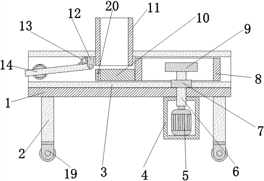
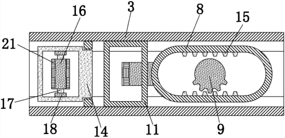
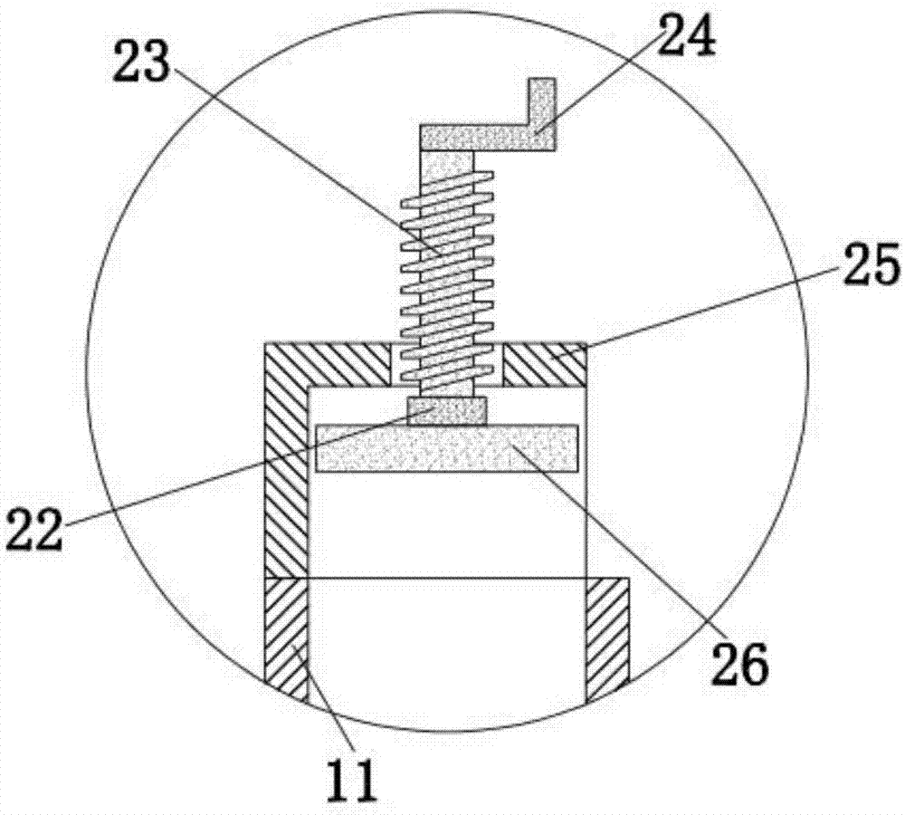
[0015] See Figure 1-3 , The present invention provides a technical solution: a fully automatic continuous conveying mechanism with an automatic compression device, which can smoothly and quickly convey the raw materials one by one for processing, including a base 1 and a pillar 2, and the bottom of the base 1 is left and right. Pillars 2 are installed on the sides. Pillars 2 are used to support the base 1. A universal wheel 19 is instal...


PUM


Abstract

The invention discloses a full-automatic continuous conveyance mechanism with an automatic tightly-pressing device. The full-automatic continuous conveyance mechanism with the automatic tightly-pressing device comprises a base and supporting columns. The left side and the right side of the base are provided with the supporting columns. The top end of the base is provided with a sliding rail. The right side of the bottom end of the base is provided with a motor box. A motor is installed in the motor box. A sliding block is arranged on the right side in the sliding rail. The sliding block is inlap joint with the sliding rail. According to the full-automatic continuous conveyance mechanism with the automatic tightly-pressing device, through cooperation of a feeding opening and an ejection plate, after workers conduct feeding, raw materials needing machining can be automatically pushed leftwards to be machined one by one; through cooperation of a baffle and a torsion spring, the raw materials can be tightly pressed and stably move in the conveyance process, the situation that the raw materials generate violent shake, so that the materials are disengaged from the rail or deviate is avoided, and the machining precision is prevented from being influenced; and in this way, the quality of a machined finished product is greatly improved, and the demand of a client is met.

Description

Technical field [0001] The invention relates to the technical field of conveying mechanisms, in particular to a fully automatic continuous conveying mechanism with an automatic compression device. Background technique [0002] At present, in the manufacturing industry, products produced from special equipment are generally designed to be discharged from slides. For situations where there is a high drop (usually higher than 600mm) and large spans between processes, large-angle long slides are used. This process will A large impact can damage the surface of the product. Therefore, products with high surface requirements cannot use this large-angle long slide design. The common method is to increase the intermediate process to realize the turnover of the product. For example, the patent application number is 201520753985.5. Including the control cabinet; the driving mechanism and the conveying mechanism are arranged at the top of the control cabinet. The patented machine cannot auto...

Claims


Application Information

Patent Timeline
Patent Type & Authority Applications(China)
IPC IPC(8): B65G47/06B65G47/82B65G47/24
Inventor 梁荣强
Owner 中山市榄商置业发展有限公司
Why Eureka
Try Eureka