Vertical tractor and screw elevator using vertical tractor

A vertical traction machine and casing technology, applied in the field of elevators, can solve problems such as brake plate noise, and achieve the effects of compact structure and convenient processing and manufacturing.

Pending Publication Date: 2018-05-08
XJ SCHINDLER XUCHANG ELEVATOR
View PDF0 Cites 2 Cited by
  • Summary
  • Abstract
  • Description
  • Claims
  • Application Information

AI Technical Summary

Problems solved by technology

The permanent magnet synchronous traction machine in common elevators is horizontal. The traction wheel rotates through the traction medium (wire rope or steel belt) to drive the car to move up and down. The

Method used


Image

  • Vertical tractor and screw elevator using vertical tractor
  • Vertical tractor and screw elevator using vertical tractor
  • Vertical tractor and screw elevator using vertical tractor

Examples


Embodiment Construction

[0023] The technical solution of the present invention will be described in detail below through specific examples.

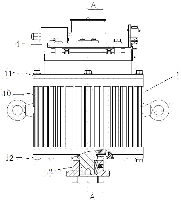
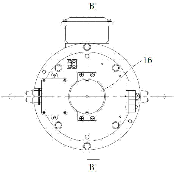
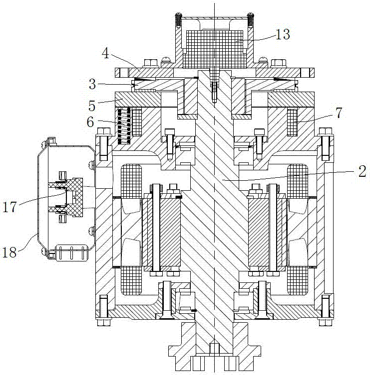
[0024] The screw elevator includes a vertical traction machine, a screw nut mechanism and a car, and the screw nut is fixedly connected to the car. Such as Figure 1 to Figure 4 As shown, the vertical traction machine includes a casing 1 and a rotating shaft 2 whose axis is fixed in the casing 1 and extends in the vertical direction. The casing includes an upper end cover 11, a lower end cover 12 and a casing between the upper and lower end covers. The main body 10, the stator 15 is embedded in the casing body 10, the upper and lower ends of the rotating shaft 2 pass through the upper end cover 11 and the lower end cover 12 respectively, the rotor 14 is fixed on the rotating shaft 2, and the lower end of the rotating shaft 2 is connected to the The leading screw is connected, and the upper end of the rotating shaft is provided with a brake.

[0025] The brake...


PUM


Abstract

The invention relates to a vertical tractor and a screw elevator using the vertical tractor. In the vertical tractor, a brake at the upper end of a rotating shaft comprises a friction disc which is assembled on the rotating shaft in a rotating stop manner and a brake plate which is positioned above the friction disc; an armature is arranged below the friction disc; a positioning shaft shoulder with an upward step surface is arranged on the rotating shaft; when an electromagnetic coil is powered off, the armature pushes the friction disc to compress the brake plate under the action of a brake spring, and a gap is reserved between the armature and the upper end surface of an upper end cover; when the electromagnetic coil is powered on, the armature moves downwards to tightly adhere to the upper end surface of the upper end cover under the action of electromagnetic force, and simultaneously, the friction disc moves downwards and is stopped above the positioning shaft shoulder under the action of gravity; and a gap is reserved between each of the upper side and the lower side of the friction disc and the brake plate as well as the armature. According to the vertical tractor and the screw elevator using the vertical tractor, limited operation of the friction disc is realized; in a release state of the brake, an air gap on the upper side and the lower side of the friction disc can beensured; and the problem that noises are easily produced when the friction disc rotates to rub the brake plate or the armature is solved.

Description

technical field [0001] The invention relates to the technical field of elevators, in particular to a vertical traction machine and a lead screw elevator using the traction machine. Background technique [0002] With the development of the construction industry and the improvement of people's living standards, the technical requirements for elevators are getting higher and higher. In order to simplify the structure and save the building area, the screw elevator is used in some occasions. The screw elevator includes a vertical traction machine and a screw nut mechanism. The vertical traction machine drives the screw to rotate, and the nut is fixedly connected to the car. . When the elevator car starts and stops, the screw elevator needs to be controlled by a braking device. The permanent magnet synchronous traction machine in common elevators is horizontal. The traction wheel rotates through the traction medium (wire rope or steel belt) to drive the car to move up and down. ...

Claims


Application Information

Patent Timeline
IPC IPC(8): B66B5/18B66B9/02B66B11/04
CPCB66B5/18B66B9/025B66B11/0446
Inventor 易小红刘成辉李京春王露阳张金丽
Owner XJ SCHINDLER XUCHANG ELEVATOR
Why Eureka
Try Eureka