
Hydraulic engineering sluice gate

A technology for water conservancy projects and gates, applied in water conservancy projects, marine engineering, coastline protection, etc., can solve problems such as unbalanced force, occurrence, and unstable operation, and achieve the effect of reducing deformation, reducing energy loss, and running stably

Inactive Publication Date: 2018-05-08
南宫市银环商贸有限公司
View PDF0 Cites 15 Cited by
  • Summary
  • Abstract
  • Description
  • Claims
  • Application Information

AI Technical Summary

Problems solved by technology

[0005] Aiming at the deficiencies of the prior art, the present invention provides a water conservancy gate, which solves the problem that when the current water conservancy gate is opened and closed, the gate body is only subjected to force at one point, resulting in unbalanced force during opening and closing, unstable operation, and easy problems that lead to accidents

Method used


Image

  • Hydraulic engineering sluice gate
  • Hydraulic engineering sluice gate

Examples


Embodiment Construction

[0019] The following will clearly and completely describe the technical solutions in the embodiments of the present invention with reference to the accompanying drawings in the embodiments of the present invention. Obviously, the described embodiments are only some, not all, embodiments of the present invention. Based on the embodiments of the present invention, all other embodiments obtained by persons of ordinary skill in the art without making creative efforts belong to the protection scope of the present invention.

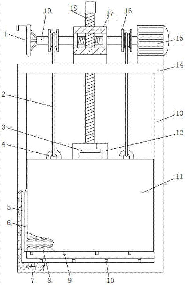
[0020] see Figure 1-2 , the present invention provides a technical solution: a water conservancy project gate, comprising a door frame 13, a top plate 14 is welded on the top of the door frame 13, a limit chute 5 is provided on the inner side of the door frame 13, and a door body 11 is arranged on the inner side of the door frame 13, The front side of the door body 11 is a convex arc surface, and the back side of the door body 11 is a vertical plane. Since th...


PUM


Abstract

The invention discloses a hydraulic engineering sluice gate. The hydraulic engineering sluice gate comprises a door frame. A top plate is welded to the top of the door frame. The inner side face of the door frame is provided with limiting sliding grooves. The inner side of the door frame is provided with a door body. Limiting sliding blocks on the two sides of the door body are slidably connectedwith the limiting sliding grooves on the two sides of the door frame. A top frame is welded to the middle portion of the upper surface of the door body. Lugs are welded to the two sides of the upper surface of the door body correspondingly. According to the hydraulic engineering sluice gate, while the door body is lifted up and down through a lead screw, and the two sides of the top of the door body are pulled and lifted up and down through two steel wire ropes, so that the door body is stressed uniformly in the lifting process, stable in operation and high in safety; a horizontal shaft is driven to rotate through a single driving motor; during rotation of the horizontal shaft, the lead screw engaged with the horizontal shaft also rotates to lift the door body up and down, reels rotate todrive the steel wire ropes to pull the door body. The hydraulic engineering sluice gate conducts driving through the driving motor in the whole process, and the synchronism is high. Meanwhile, energyconsumption is reduced, and the design is reasonable.

Description

technical field [0001] The invention relates to the technical field of water conservancy engineering, in particular to a water conservancy engineering gate. Background technique [0002] The gate is used to close and open the control facility of the discharge (discharge) channel. An important part of hydraulic structures, it can be used to intercept water flow, control water level, regulate flow, discharge sediment and floating objects, etc. According to the production materials, there are mainly wooden gates, wooden panel steel frame gates, cast iron gates, reinforced concrete gates and steel gates. According to the relative position of the top of the gate and the horizontal plane, there are mainly open-top gates and submerged gates. According to the nature of work, there are mainly working gates, emergency gates and maintenance gates. Divided according to the gate opening and closing method, there are mainly mechanically operated gates and hydraulic automatic gates cont...

Claims


Application Information

Patent Timeline
Patent Type & Authority Applications(China)
IPC IPC(8): E02B7/36E02B7/28E02B7/34
CPCE02B7/36E02B7/28E02B7/34
Inventor 杨昆
Owner 南宫市银环商贸有限公司
Learn More