System for cutting of reinforced concrete grouped piles through shield machine

A reinforced concrete and shield technology, which is applied in the direction of earth drilling, mining equipment, tunnels, etc., can solve problems such as difficult removal of muck, wear of cutterhead and tool, excessive settlement of pile foundation, etc., and achieve improved transportation capacity and enhanced The strength of the cutter head and the effect of ensuring safety

Pending Publication Date: 2018-05-08
BEIJING JIAOTONG UNIV
View PDF0 Cites 3 Cited by
  • Summary
  • Abstract
  • Description
  • Claims
  • Application Information

AI Technical Summary

Problems solved by technology

[0003] However, the cutting of large-diameter reinforced concrete piles is different from conventional rock and soil. How to ensure the safety of the shield machine and the existing piles during the excavation process, reduce the wear of the shield machine, and improve the construction efficiency is the use of shield cutting. Difficulties of Large Diameter Reinforced Concrete Pile Group
Although the existing shield pile cutting system has been improved in the shield propulsion system and cutter configuration, there are still problems such as difficult removal of slag, serious wear of the cutter head and cutter, excessive settlement of the pile foundation, wear of the outer casing, and the construction of the shield machine. Too high temperature and many other problems make it difficult to perform this task well

Method used


Image

  • System for cutting of reinforced concrete grouped piles through shield machine
  • System for cutting of reinforced concrete grouped piles through shield machine
  • System for cutting of reinforced concrete grouped piles through shield machine

Examples


Embodiment Construction

[0033] Embodiments of the present invention are described in detail below, examples of which are shown in the drawings, wherein the same or similar reference numerals denote the same or similar elements or elements having the same or similar functions throughout. The embodiments described below by referring to the figures are exemplary only for explaining the present invention and should not be construed as limiting the present invention.

[0034] Those skilled in the art will understand that unless otherwise stated, the singular forms "a", "an", "said" and "the" used herein may also include plural forms. It should be further understood that the word "comprising" used in the description of the present invention refers to the presence of said features, integers, steps, operations, elements and / or components, but does not exclude the presence or addition of one or more other features, Integers, steps, operations, elements, components, and / or groups thereof. It will be understoo...


PUM


Abstract

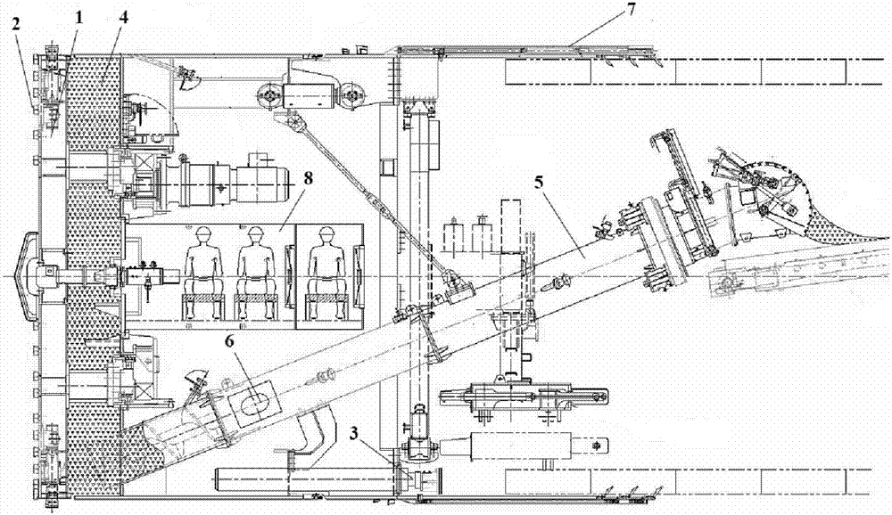
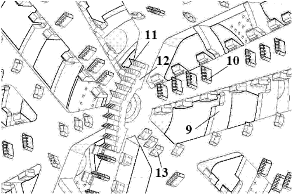
The invention provides a system for cutting of reinforced concrete grouped piles through a shield machine. The system comprises a cutting unit, a propelling unit, a residue soil treatment unit, a monitoring unit and a control unit. The cutting unit is composed of a circular cutter disc and a plurality of cutters mounted on the circular cutter disc, and used for cutting residue soil, the propellingunit is composed of a jack and a propelling pump and used for propelling the cutting unit, a residue soil improvement unit of the residue soil treatment unit improves the cut residue soil, and then the residue soil is conveyed out through a spiral conveyor. The monitoring unit transmits sedimentation monitoring data of the ground and a building to the control unit in real time so as to enable thecontrol unit to adjust the tunneling parameters of the propelling unit. According to the system for cutting of the reinforced concrete grouped piles through the shield machine, the cutter configuration scheme and form are improved, the strength of the cutter disc is reinforced, the conveying capacity of the spiral conveyor is improved, and a novel foaming agent for residue soil improvement, standard thick grout for wall back grouting for improvement of other shield machine structures are proovided so that the existing shield machine can better adapt to construction of cutting of the large-diameter reinforced concrete grouped piles, and meanwhile the safety of the cut pile bodies can be ensured.

Description

technical field [0001] The invention relates to the technical field of underground construction engineering, in particular to a shield cutting reinforced concrete pile group system. Background technique [0002] In the new period of construction and development of urban underground roads in my country, more and more underground buildings (structures) such as tunnels are built using shield tunneling methods. Concrete pile foundation obstacles occur from time to time. Considering that conventional shield machines basically do not have the ability to cut piles, traditional methods such as dismantling the original building (structure), pulling piles from the ground, and digging piles after shaft excavation are generally selected. Remove pile foundations. Compared with the traditional method, the direct cutting of the pile foundation by the shield machine has the advantages of small impact on the surrounding environment, low cost, short construction period, etc., and has significa...

Claims


Application Information

Patent Timeline
IPC IPC(8): E21D9/08E21D9/12
CPCE21D9/003E21D9/0685E21D9/08E21D9/124
Inventor 袁大军王飞王占生穆永江毛家骅高振峰
Owner BEIJING JIAOTONG UNIV
Why Eureka
Try Eureka