

Unmanned aerial vehicle self-localization and pose regulation technology based on ground identifications
An unmanned aerial vehicle and autonomous positioning technology, applied to instruments, measuring devices, etc., can solve problems such as poor positioning accuracy, poor indoor positioning effect, and high price
- Summary
- Abstract
- Description
- Claims
- Application Information
AI Technical Summary
Problems solved by technology
Method used
Image


Examples
specific Embodiment approach 1
[0057] Specific implementation mode one: combine figure 1 To describe this embodiment,
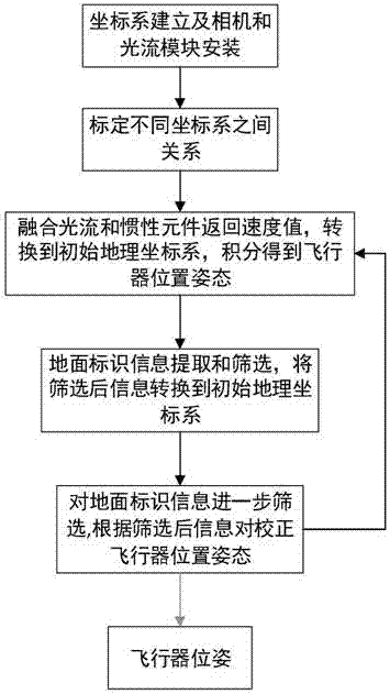
[0058] A technology for autonomous positioning and pose correction of unmanned aerial vehicles based on ground markings, comprising the following steps:
[0059] Step 1. Establish the initial geographic coordinate system, the body coordinate system, the body-to-geography implicated coordinate system, the camera coordinate system, the image coordinate system, the optical flow module coordinate system, and install the camera and the optical flow positioning module on the UAV;
[0060] Step 2, calibrate the position and attitude of the camera coordinate system relative to the body coordinate system, measure the relative positional relationship between the optical flow positioning module and the camera, and calibrate the transformation matrix between the body coordinate system and the initial geographic coordinate system;
[0061] Step 3, obtain the velocity information of the optical flow po...
specific Embodiment approach 2
[0067] The specific process of step 1 of this embodiment includes the following steps:
[0068] Step 11, the initial geographic coordinate system o 0 x 0 the y 0 z 0 : Take the east-north-sky coordinate system of the location of the UAV as the initial geographic coordinate system;
[0069] Body coordinate system o b x b the y b z b : Take the center of gravity of the UAV as the origin of the body coordinate system o b , the direction parallel to the axis pointing to the nose of the UAV in the longitudinal symmetry plane is x b Axis, pointing to the right perpendicular to the longitudinal symmetry plane of the UAV is y b axis, perpendicular to x b axis and y b Axis pointing down the UAV is z b axis;
[0070] Airframe to geographic implicated coordinate system o 1 x 1 the y 1 z 1 : Take the center of gravity of the UAV as the origin of the body coordinate system o 1 , x 1 、y 1 ,z 1 The axes are respectively parallel to the initial geographic coordinate syste...
specific Embodiment approach 6
[0095] The specific process of Step 5 of this embodiment is as follows:
[0096] Step 51: Under the initial geographic coordinate system, use the position and angle of the unmanned aerial vehicle, the position and angle of the straight line after preliminary screening under the initial geographic coordinate system, and the relationship between the straight lines after preliminary screening to further screen the straight line, delete the position, The straight line whose angle is too different from the real value, delete the non-parallel and non-perpendicular line with other straight lines.
[0097] Step 52: Process the information of the straight line after further screening, and in the initial geographic coordinate system, make a difference between the real position of the straight line after screening and the detected position of the straight line after screening, and the result is the UAV position correction amount ΔP.
[0098] When there is only one straight line informati...
PUM
 Abstract
Description
Claims
Application Information