Imaging system

An imaging system and imaging unit technology, applied in the field of zoom imaging systems, can solve problems such as poor imaging quality at night, and achieve the effects of improving service life, transparent imaging quality, and simple structure

Pending Publication Date: 2018-05-08
舜宇光学(中山)有限公司
View PDF0 Cites 0 Cited by
  • Summary
  • Abstract
  • Description
  • Claims
  • Application Information

AI Technical Summary

Problems solved by technology

[0004] The purpose of the present invention is to provide an imaging system to solve the problem of poor imaging quality of the imaging system at night

Method used


Image

  • Imaging system
  • Imaging system
  • Imaging system

Examples


Embodiment approach

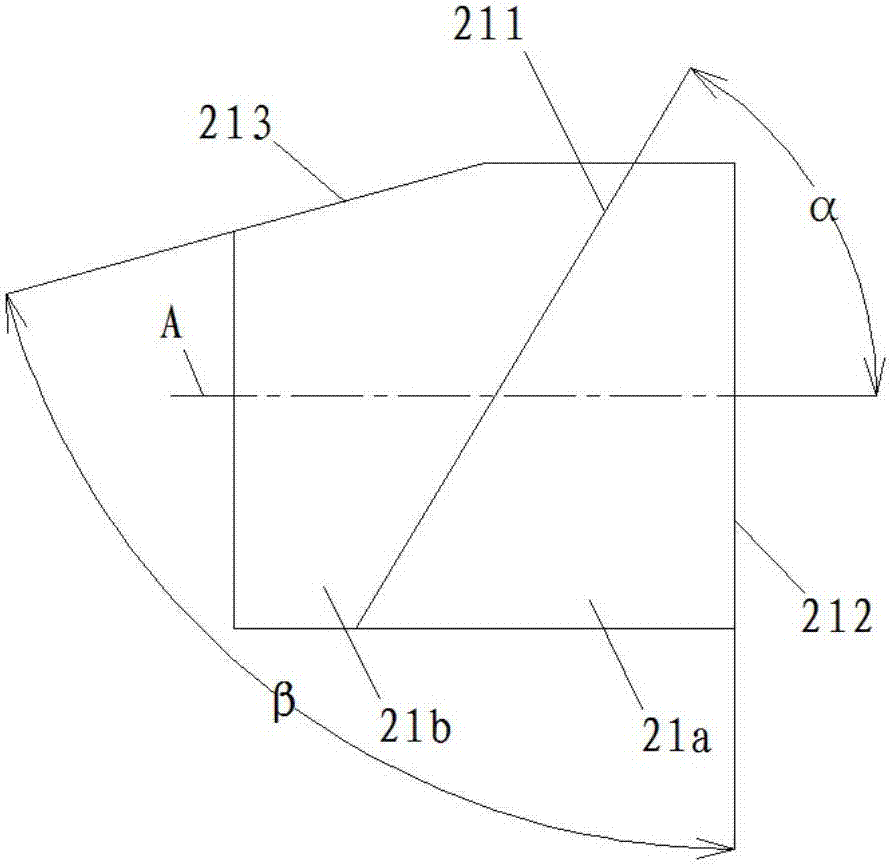
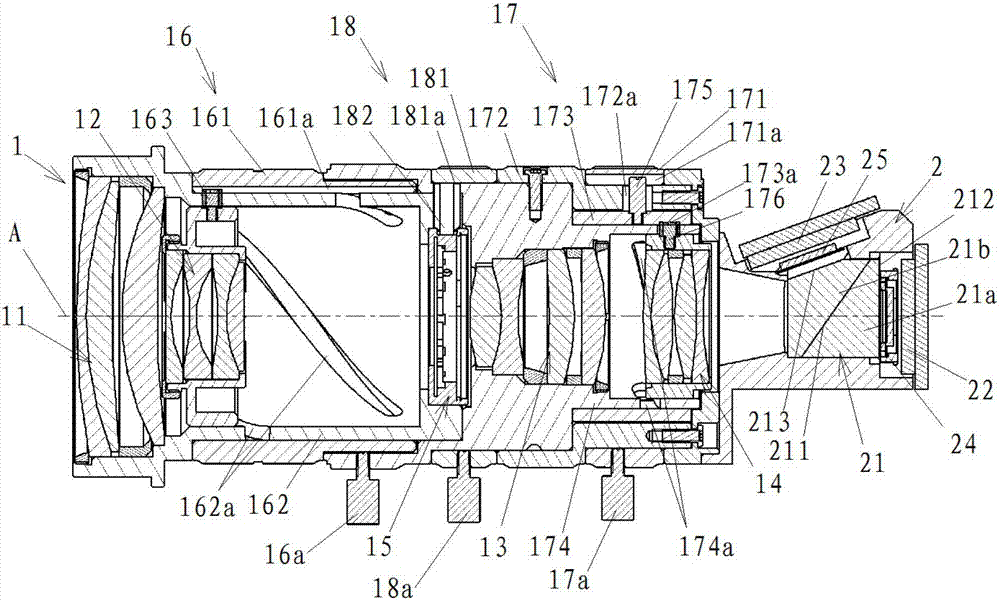
[0053] Such as figure 1 As shown, according to an embodiment of the present invention, the third driving mechanism 18 includes: an aperture adjusting ring 181 and an aperture connecting nail 182 . In this embodiment, the diaphragm 15 is installed between the first cylinder 162 and the second inner cylinder 174 . The diaphragm adjusting ring 181 is mounted on the outside of the second inner cylinder 174 so as to be rotatable relative to the second inner cylinder 174 . In this embodiment, one end of the diaphragm connecting nail 182 is connected to the diaphragm adjusting ring 181 , and the other end is connected to the diaphragm 15 . In this embodiment, the aperture adjustment ring 181 has an aperture adjustment guide groove 181a parallel to the axial direction. One end of the diaphragm connecting nail 182 is connected with the diaphragm adjusting guide groove 181 a , and the other end is fixedly connected with the diaphragm 15 . The adjustment of the aperture of the light-t...


PUM


Abstract

The invention relates to an imaging system. The imaging system includes an optical unit and an imaging unit, wherein the optical unit includes successively arranged first battery of lens with positivefocal power, second battery of lens with negative focal power, third battery of lens with positive focal power, and fourth battery of lens with positive focal power from the object side to the imaging side; and the imaging unit includes a prism, a first photosensitive chip for receiving the visible light and a second photosensitive chip for receiving the infrared light. Through the above setting,the structure of the whole optical unit is compact; the optical unit and the first photosensitive chip in the imaging unit are coordinated to realize clear imaging under visible light conditions in the daytime; the optical unit and the first photosensitive chip and the second photosensitive chip of the imaging unit are coordinated, and common imaging of the infrared light and the visible light isused to realize consideration of brightness and colors under weak visible light conditions in the night at the same time, thus fully restoring the real environment and the object appearance of the night and enabling the imaging quality to be clear and transparent and the contour to be distinct.

Description

technical field [0001] The present invention relates to an imaging system, in particular to a zoom imaging system. Background technique [0002] With the development of society, people's awareness of safety precautions has been continuously improved, so the security monitoring industry has also developed rapidly, and monitoring has played an increasingly important role. In particular, the introduction of high-definition imaging systems has greatly improved the effectiveness of monitoring. However, common surveillance imaging systems are mainly designed for daytime visible light conditions, and surveillance targets can only be seen under visible light conditions. Since the visible light at night cannot meet the imaging requirements of ordinary surveillance imaging systems, night surveillance is gradually being valued in many surveillance situations. Although the pixels of the imaging system are getting higher and higher, the night vision effect is still difficult to meet th...

Claims


Application Information

Patent Timeline
Patent Type & Authority Applications(China)
IPC IPC(8): G02B7/00G02B7/10G03B17/14H04N5/225H04N5/232
CPCG02B7/00G02B7/006G02B7/10G03B17/14H04N23/50H04N23/55H04N23/667
Inventor 凌云辉梁伟朝翟林燕付湘发
Owner 舜宇光学(中山)有限公司
Why Eureka
Try Eureka