Method and device for power supply control of FPGA accelerator card auxiliary power supply, and medium

An auxiliary power supply and power supply control technology, applied in the field of FPGA development, can solve problems such as low efficiency, auxiliary power safety hazards, insufficient power supply to support normal work, etc., to achieve the effect of improving flexibility and reducing waste

Inactive Publication Date: 2018-05-08
ZHENGZHOU YUNHAI INFORMATION TECH CO LTD
View PDF5 Cites 7 Cited by
  • Summary
  • Abstract
  • Description
  • Claims
  • Application Information

AI Technical Summary

Problems solved by technology

[0003] Based on the specifications of the PCIE protocol, the design of the power supply system of the PFGA accelerator card needs to follow the restrictions of the PCIE protocol. According to different interface combinations, the maximum power that the slot part can provide is 75W. However, for mid-to-high-end FPGA accelerator cards, The power supply of 75W is not enough to support its normal work, and it is necessary to increase the auxiliary power supply of the PCIE interface according to the specific situation. Since the power supply of the auxiliary power supply is relatively large, but the FPGA components and other working components in the FPGA accelerator card are working. , the demand for power supply power varies according to the actual working conditions. Therefore, the current use of auxiliary power supplies is inflexible and relatively inefficient. At the same time, unreasonable use of auxiliary power supplies with high power supply will also cause damage to the FPGA accelerator card. The various components in the device bring hidden dangers to safety

Method used


Image

  • Method and device for power supply control of FPGA accelerator card auxiliary power supply, and medium
  • Method and device for power supply control of FPGA accelerator card auxiliary power supply, and medium

Examples


Embodiment 1

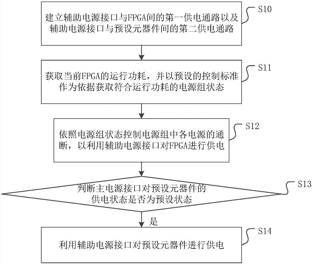
[0040] figure 1 It is a flowchart of a power supply control method for an FPGA accelerator card auxiliary power supply provided by an embodiment of the present invention. Please refer to figure 1 , the specific steps of the power supply control method of the FPGA accelerator card auxiliary power supply include:

[0041] Step S10: Establishing a first power supply path between the auxiliary power interface and the FPGA and a second power supply path between the auxiliary power interface and preset components.

[0042] Wherein, a power supply group is included in the first power supply path, and the power supply group is composed of N power supplies connected in parallel, and the on-off of each power supply is controllable; wherein, N is a positive integer greater than 1.

[0043] It should be noted that the auxiliary power interface is a power supply interface activated when the power consumption required by the FPGA accelerator card cannot be met by the main power interface,...

Embodiment 2

[0053] Based on the above embodiments, as a preferred implementation manner, the preset components specifically include a circuit fan and a linear voltage regulator.

[0054] It should be noted that circuit fans are usually used to cool down components including FPGAs, so as to relatively reduce their additional power consumption at high temperatures. Linear voltage regulators are usually used to supply power to certain low-power components. By connecting certain logic components and supplying power to the logic components, the predetermined control logic of the logic components can be executed.

[0055] This embodiment provides an application scenario. The ES1030 logic chip is connected to the ES1030 logic chip through the linear voltage regulator LDO. Provide power supply to ensure the normal operation of the FPGA. In addition, a TL331 chip can also be added as a comparator for judging whether the preset conditions are met before power-on or power-off. This application scen...

Embodiment 3

[0071] The embodiment of a power supply control method for an FPGA accelerator card auxiliary power supply has been described in detail above, and the present invention also provides a power supply control device for an FPGA accelerator card auxiliary power supply, because the embodiment of the device part and the method part The embodiments correspond to each other, so for the embodiments of the device part, please refer to the description of the embodiments of the method part, and details will not be repeated here.

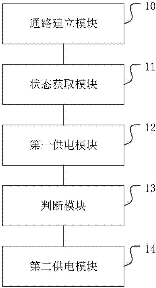
[0072] figure 2 A structural diagram of a power supply control device for an FPGA accelerator card auxiliary power supply provided by an embodiment of the present invention. Such as figure 2 As shown, a power supply control device for an FPGA accelerator card auxiliary power supply provided by an embodiment of the present invention includes:

[0073] The path establishment module 10 is configured to establish a first power supply path between the auxiliary p...


PUM


Abstract

The invention discloses a method and a device for power supply control of a FPGA accelerator card auxiliary power supply, and a medium. The steps of the method comprises: establishing a first power supply access between an auxiliary power interface and a FPGA, and a second power supply access between an auxiliary power interface and a preset component; obtaining current operation power consumptionof the FPGA, and using a preset control standard as basis, obtaining a power supply group state which meets the operation power consumption; according to the power supply group state, controlling on-off of each power supply in the power supply group, to supply power for the FPGA using the auxiliary power interface; determining whether the state of the main power interface supplying power to the preset component is a preset state, if yes, using the auxiliary power interface to supply power for the preset component. An auxiliary power supply is relatively reasonably and flexibly used, and safety operation of each component and integrated working efficiency are guaranteed. In addition, the invention also provides a device for power supply control of a FPGA accelerator card auxiliary power supply, and a medium, and beneficial effects are as described above.

Description

technical field [0001] The invention relates to the field of FPGA development, in particular to a power supply control method, device and medium for an FPGA accelerator card auxiliary power supply. Background technique [0002] FPGA chips can achieve high computing performance for specific operations including artificial neural networks, and their performance is usually higher than general-purpose processors such as CPUs or GPUs at the same power consumption, so they are often used as auxiliary processors to achieve acceleration The effect of the operation. FPGA usually needs to cooperate with the main processor to realize functions, and usually exists physically in the form of a board with a PCIE interface, which is called an FPGA accelerator card. [0003] Based on the specifications of the PCIE protocol, the design of the power supply system of the PFGA accelerator card needs to follow the restrictions of the PCIE protocol. According to different interface combinations, ...

Claims


Application Information

Patent Timeline
Patent Type & Authority Applications(China)
IPC IPC(8): G06F1/26G06F1/28G06F1/32
Inventor 陈三霞
Owner ZHENGZHOU YUNHAI INFORMATION TECH CO LTD
Why Eureka
Try Eureka