Composite DC power transmission equipment

A kind of direct current transmission equipment and direct current transmission technology, which is applied in the direction of electrical components, power transmission AC network, emergency protection circuit device, etc., can solve the problems of large loss and high cost of direct current transmission system, and achieve the purpose of saving floor area, reducing loss and saving cost effect

Inactive Publication Date: 2018-05-08
GLOBAL ENERGY INTERCONNECTION RES INST CO LTD
View PDF5 Cites 5 Cited by
  • Summary
  • Abstract
  • Description
  • Claims
  • Application Information

AI Technical Summary

Problems solved by technology

[0006] Therefore, the technical problem to be solved by the present invention is that the power flow control and fault isolation methods of the existing DC transmission system have large loss and high cost

Method used


Image

  • Composite DC power transmission equipment
  • Composite DC power transmission equipment
  • Composite DC power transmission equipment

Examples


Embodiment Construction

[0040] The technical solutions of the present invention will be clearly and completely described below in conjunction with the accompanying drawings. Apparently, the described embodiments are some of the embodiments of the present invention, but not all of them. Based on the embodiments of the present invention, all other embodiments obtained by persons of ordinary skill in the art without making creative efforts belong to the protection scope of the present invention.

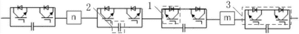
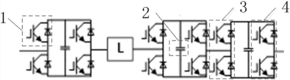
[0041] The present invention also provides a compound direct current transmission equipment, such as figure 2 , Figure 4 , Figure 5 shown, including:

[0042] Fault isolation unit 11, such as figure 2 As shown, it includes: a plurality of first power electronic switch units connected in series, the first power electronic switch unit includes a first switch branch 3 and a first capacitor 2, and the first switch branch 3 includes at least two power electronic switches connected in series 1. The first cap...


PUM


Abstract

The invention provides composite DC power transmission equipment. The equipment comprises a fault isolation unit including a plurality of first power electronic switch units connected in series, a flow control unit which is connected to the fault isolation unit and is used for controlling the flow distribution between converter stations, and a control unit which is connected to the fault isolationunit and the flow control unit and is used for controlling the flow control unit and the fault isolation unit to execute preset action, wherein each of the first power electronic switch units comprises a first switch branch and a first capacitor, the first switch branch comprises at least two power electronic switches connected in series, and the first capacitor is connected at two ends of the first switch branch in parallel. Through mutually connected DC isolation unit, flow control unit and control unit, the fault isolation of DC power transmission is achieved, compared with a scheme of using a unified power flow controller and a conventional circuit breaker, the cost is saved, the loss is reduced, and the floor space is saved.

Description

technical field [0001] The invention relates to the technical field of DC power transmission in electric power systems, in particular to a composite DC power transmission device. Background technique [0002] Flexible DC transmission is an important technical means for the development of smart grids. Compared with conventional DC transmission methods, flexible DC transmission has strong technical advantages in island power supply, interconnection of large-scale AC systems, and new energy grid integration. development prospects. [0003] The DC power grid established based on the flexible DC system is an effective solution to realize wide-area coordinated complementarity and reliable transmission of large-scale renewable energy, and is an important application direction of high-voltage and large-capacity flexible DC in the future. The development of DC power grids faces many challenges including DC fault protection and DC power flow control. Solving the two challenges of DC...

Claims


Application Information

Patent Timeline
Patent Type & Authority Applications(China)
IPC IPC(8): H02J3/36H02H7/26
CPCH02H7/26H02J3/36Y02E60/60
Inventor 常彬贺之渊刘栋林畅江晨闫鹤鸣高路谷怀广李方媛
Owner GLOBAL ENERGY INTERCONNECTION RES INST CO LTD
Why Eureka
Try Eureka