Method for installing magnetic steel in circular hole

A magnetic steel and round hole technology, which is applied in electromechanical devices, manufacturing motor generators, manufacturing stator/rotor bodies, etc., can solve problems such as rework difficulties, assembly difficulties, and magnetic steel scrapping, so as to overcome magnetic effects and reduce assembly rework The effect of efficiency and saving assembly cost

Active Publication Date: 2018-05-08
山东重心电子科技有限公司
View PDF4 Cites 0 Cited by
  • Summary
  • Abstract
  • Description
  • Claims
  • Application Information

AI Technical Summary

Problems solved by technology

When combined, since the material of the magnetic steel and auxiliary magnetic steel is NdFeB371 / 138 soft magnetic alloy, it has a large magnetic force after magnetization, and the material of the motor yoke is iron cobalt vanadium soft magnetic alloy 1J22, which itself is also It has a certain degree of magnetism. When assembling, due to the magnetic attraction or mutual repulsion between the various parts, it brings great difficulties to the assembly. If the parts cannot be placed and fixed according to the assembled position at one time, it will cause rework. Difficulties and scrapping of magnetic steel, resulting in a lot of waste

Method used


Image

  • Method for installing magnetic steel in circular hole
  • Method for installing magnetic steel in circular hole
  • Method for installing magnetic steel in circular hole

Examples


Embodiment Construction

[0049] Attached below Figure 1-22 Embodiments of the present invention are described.

[0050] The method for installing the magnetic steel in the circular hole includes the following installation steps:

[0051] Step 1: Install the yoke body 1 into the fixture base 4 for fixing, such as Figure 12 shown;

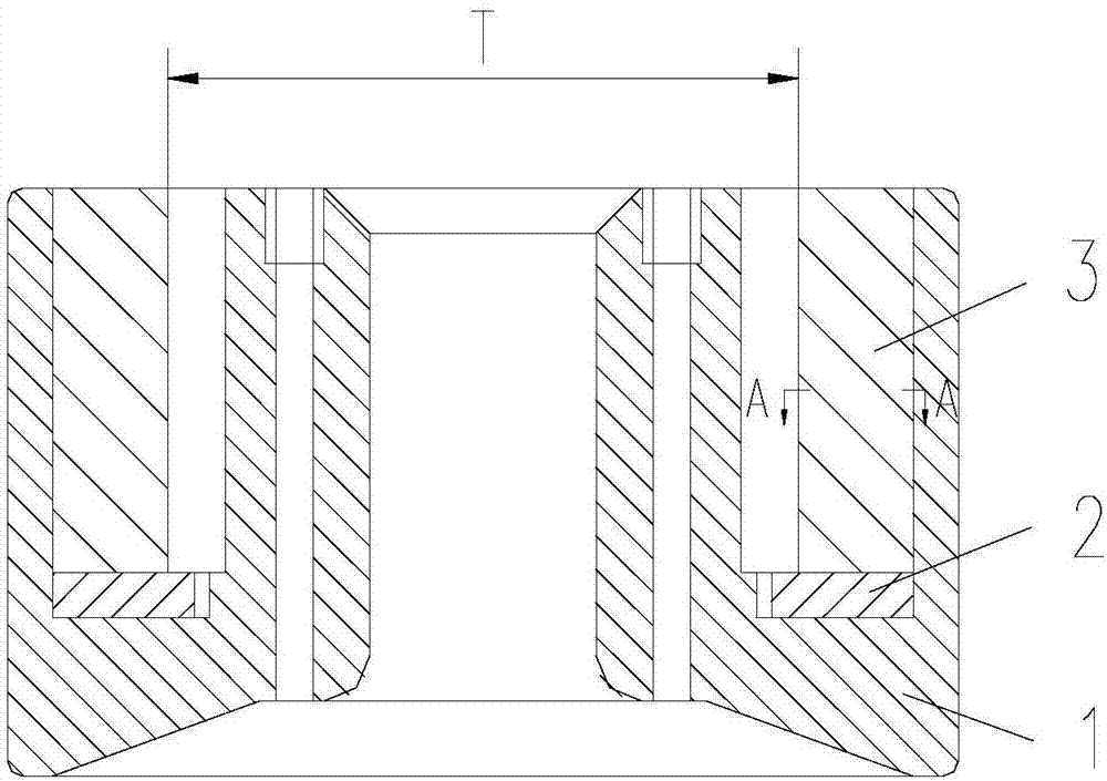
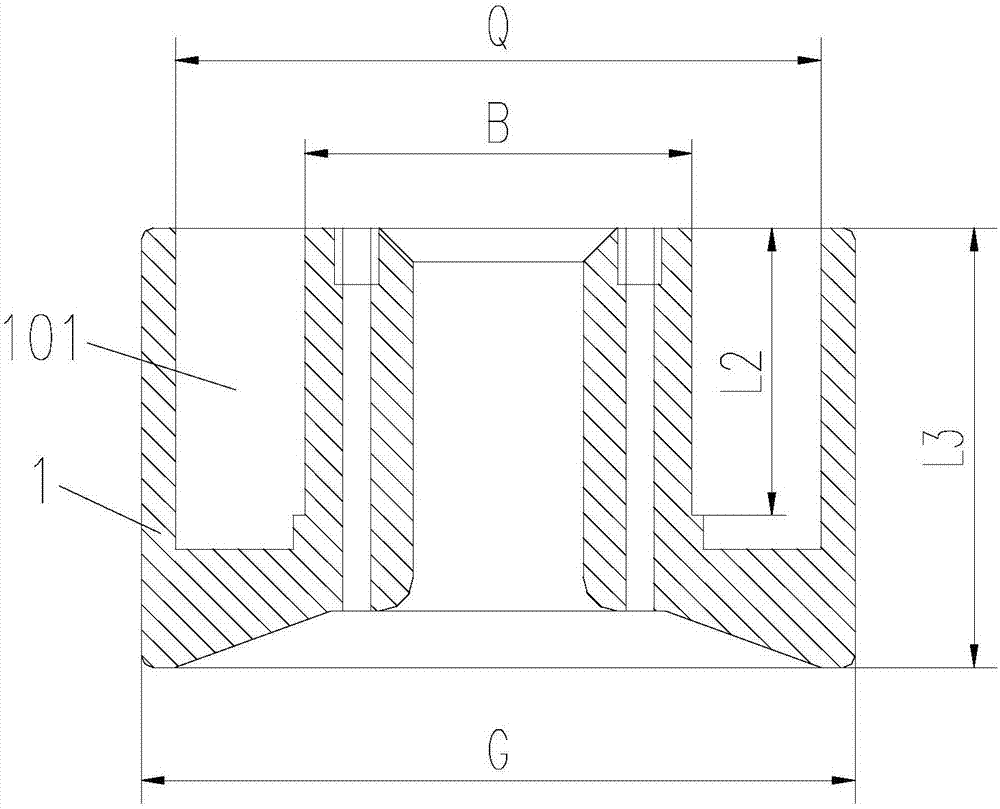
[0052] Specifically, such as Figure 5 and 2 As shown, the center of the clamp base 4 is formed with a hole I401 adapted to fit into the yoke body 1, and the difference between the dimensions L7 and L6 in the height direction of the hole I401 is smaller than the height L3 of the yoke body 1; The cylindrical surface with a diameter G of the body 1 is in clearance fit with the cylindrical surface with a diameter F in the hole I401 of the clamp base 4 with a clearance greater than 0.01 mm.

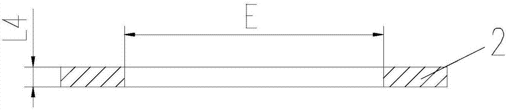
[0053] Step 2: Install the auxiliary magnetic steel 2 on the bottom of the auxiliary magnetic steel installation fixture 5, then insert the auxiliary magnetic steel installation fixtur...


PUM


Abstract

The invention relates to a method for installing magnetic steel in a circular hole. The method comprises the steps of loading a yoke body into a fixture base, installing auxiliary magnetic steel by anauxiliary magnetic steel installing fixture and an auxiliary magnetic steel pushing fixture, loading a magnetic steel loaded positioning block into the yoke body, loading simulated magnetic steel into the yoke body, replacing a first piece of the simulated magnetic steel with a first piece of magnetic steel, compressing by a pressing plate structure, replacing a second piece of the simulated magnetic steel adjacent to the first piece of magnetic steel with a second piece of magnetic steel, pushing the second piece of magnetic steel to be next to the first piece of magnetic steel through rotating the compressing device, and compressing the first piece of magnetic steel and the second piece of magnetic steel by the pressing plate structure; installing the left magnetic steel according to the replacement method of the second piece of magnetic steel; fastening the yoke body and the magnetic steel loaded positioning block by using a magnetic steel fastening device, taking the yoke body outfrom the fixture base, performing position fixation, and completing the installation. The magnetic steel is installed by adopting the special assembly fixtures and the specific technological method,thereby being excellently controlling the assembling process of the magnetic steel, meeting assembly requirements of the magnetic steel, having high positioning accuracy, being simple and practical inassembly technological process, capable of installing in place in one time, and reducing the assembly rework rate.

Description

technical field [0001] The invention belongs to the technical field of mechanical assembly, and in particular relates to a method for installing magnetic steel in a circular hole. Background technique [0002] In the actual production process, we often encounter such figure 2 A part of the type of motor yoke shown, where a hole such as image 3 The auxiliary magnetic steel shown, and install multiple pieces such as Figure 4 magnets shown, and finally formed as figure 1 Magnet mounting assembly shown. When combined, since the material of the magnetic steel and auxiliary magnetic steel is NdFeB371 / 138 soft magnetic alloy, it has a large magnetic force after magnetization, and the material of the motor yoke is iron cobalt vanadium soft magnetic alloy 1J22, which itself is also It has a certain degree of magnetism. When assembling, due to the magnetic attraction or mutual repulsion between the various parts, it brings great difficulties to the assembly. If the parts cannot...

Claims


Application Information

Patent Timeline
Patent Type & Authority Applications(China)
IPC IPC(8): H02K15/03
CPCH02K15/03
Inventor 吕芸芬师永强夏建强
Owner 山东重心电子科技有限公司
Why Eureka
Try Eureka