
Circuit board shielding case component inserter

A shielding cover, plug-in machine technology, applied in electrical components, printed circuits, electrical components and other directions, can solve the problems affecting quality and efficiency, unable to mount production, expensive and other problems, to improve production efficiency, low manufacturing cost, equipment Flexible and strong effect

Inactive Publication Date: 2018-05-08
苏州泓舰自动化科技有限公司
View PDF12 Cites 3 Cited by
  • Summary
  • Abstract
  • Description
  • Claims
  • Application Information

AI Technical Summary

Problems solved by technology

[0003] 1) Mainly rely on imports, the brands include NXT, Panasonic, Siemens and YAMAHA, etc., which are expensive
[0004] 2) Its feeder is a coil feeder and a coil feeder. The coil feeder is a universal type, and all parts are packaged in rolls. During the production and retrieving process, the machine will automatically roll each piece of material into the phase. The corresponding distance is mainly suitable for smaller parts; when the part size is larger than a certain size and cannot be made into a roll, only the coil feeder can be used, but the coil feeder only allows one coil at a time , which requires the operator to change the tray continuously, wasting manpower and inefficiency
[0005] 3) Among all parts of PCB, SMT placement machines for smaller products can be mounted, but there are limitations in the production of parts with larger sizes (mainly referring to length and width greater than 35 mm) with placement machines. Larger products (length and width greater than 60 mm and height greater than 15 mm) cannot be mounted and produced by standard SMT placement machines. At present, domestic SMT manufacturers are manually mounted when mounting large parts, which affects Quality and efficiency without wasting manpower

Method used


Image

  • Circuit board shielding case component inserter
  • Circuit board shielding case component inserter
  • Circuit board shielding case component inserter

Examples


Embodiment

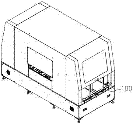
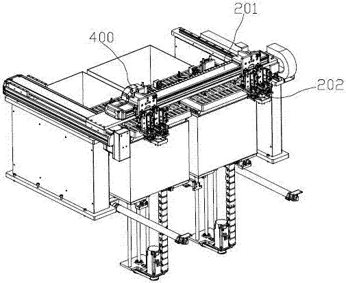
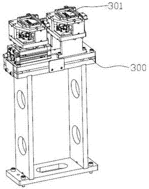
[0027] refer to Figure 1-4 , a circuit board shielding cover plug-in machine, including a feeder 100, a reclaimer, a detection table 300, a horizontal multi-joint robot 400 and a PCB circuit board moving assembly; The reclaimer is composed of a linear module 201 and an electromagnetic suction head 202. The electromagnetic suction head 202 is fixed on the slide table of the linear module 201. distribution and are all located below the linear module 201; the horizontal multi-joint robot 400 is provided with an electromagnetic chuck 401, and the PCB circuit board moving assembly is composed of a guide rail and an electric gripper 500 movably arranged on the guide rail. After the horizontal multi-joint robot 400 rotates at a certain angle, the electromagnetic chuck 401 corresponds to the detection table 300 , and after rotating at a certain angle, the electromagnetic chuck 401 corresponds to the electric gripper 500 .

[0028] When working, the whole box of material trays with p...


PUM


Abstract

The present invention discloses a circuit board shielding case component inserter. The circuit board shielding case component inserter comprises a feeder, a material taking device, a detection bench,a horizontal articulated robot and a PCB mobile module. The feeder is formed by a lifting platform and a tray fixed on the lifting platform; the material taking device is formed by a linear module andan electromagnetic suction nozzle; the electromagnetic suction nozzle is fixed on a sliding bench of the linear module; the lifting platform and the detection bench are distributed in a direction ofthe linear module and are uniformly distributed below the linear module; the horizontal articulated robot is provided with an electromagnetic chuck; the PCB mobile module is formed by a guide rail andan electric clamping jaw movably arranged on the guide rail; when the horizontal articulated robot rotates at a certain angle, the electromagnetic chuck corresponds to the detection bench, and then the horizontal articulated robot further rotates at a certain angle, the electromagnetic chuck corresponds to the electric clamping jaw, and therefore, the manufacturing cost is low, the feeding by cases saves manpower, the compatibility is good, and the circuit board shielding case component inserter is suitable for parts with various sizes.

Description

technical field [0001] The invention belongs to the technical field of automation equipment in the PCB circuit board assembly industry, in particular to a circuit board shielding cover plug-in machine. Background technique [0002] The common equipment in the PCB circuit board assembly and production industry is the SMT placement machine. Its composition structure includes: linear module, grating ruler, vacuum suction head, cam single-action suction head, industrial camera, feeder, etc., with an accuracy of within 0.05 mm. , the market demand is huge. It has the following defects: [0003] 1) Mainly rely on imports, the brands include NXT, Panasonic, Siemens and YAMAHA, etc., which are expensive. [0004] 2) Its feeder is a coil feeder and a coil feeder. The coil feeder is a universal type, and all parts are packaged in rolls. During the production and retrieving process, the machine will automatically roll each piece of material into the phase. The corresponding distance...

Claims


Application Information

Patent Timeline
IPC IPC(8): H05K3/30H05K13/04H05K13/08
CPCH05K3/306H05K13/0408H05K13/08H05K2201/10371H05K2203/16
Inventor 米鹏飞
Owner 苏州泓舰自动化科技有限公司
Learn More