Slurry turnover tank and method avoiding viscosity difference of slurry in turnover tank

A turnover tank and slurry technology, which is applied in the direction of rotary piston pumps, liquid fuel engines, rotary piston machines, etc., can solve the problems of viscosity difference and difficulty in guaranteeing the coating surface density, and achieve the goal of reducing production noise and avoiding air bubbles Effect

Inactive Publication Date: 2018-05-11
SHANXI CHANGZHENG POWER TECH CO LTD
View PDF0 Cites 1 Cited by
  • Summary
  • Abstract
  • Description
  • Claims
  • Application Information

AI Technical Summary

Problems solved by technology

[0005] Aiming at the above-mentioned technical problems in the related art, the present invention proposes a slurry turnover tank, which can solve the problem that the viscosity of the slurry in the tank is different due to the sedimentation of the slurry, which in turn makes it difficult to guarantee the density of the coating surface

Method used


Image

  • Slurry turnover tank and method avoiding viscosity difference of slurry in turnover tank

Examples


Embodiment Construction

[0023] The following will clearly and completely describe the technical solutions in the embodiments of the present invention with reference to the accompanying drawings in the embodiments of the present invention. Obviously, the described embodiments are only some, not all, embodiments of the present invention. All other embodiments obtained by persons of ordinary skill in the art based on the embodiments of the present invention belong to the protection scope of the present invention.

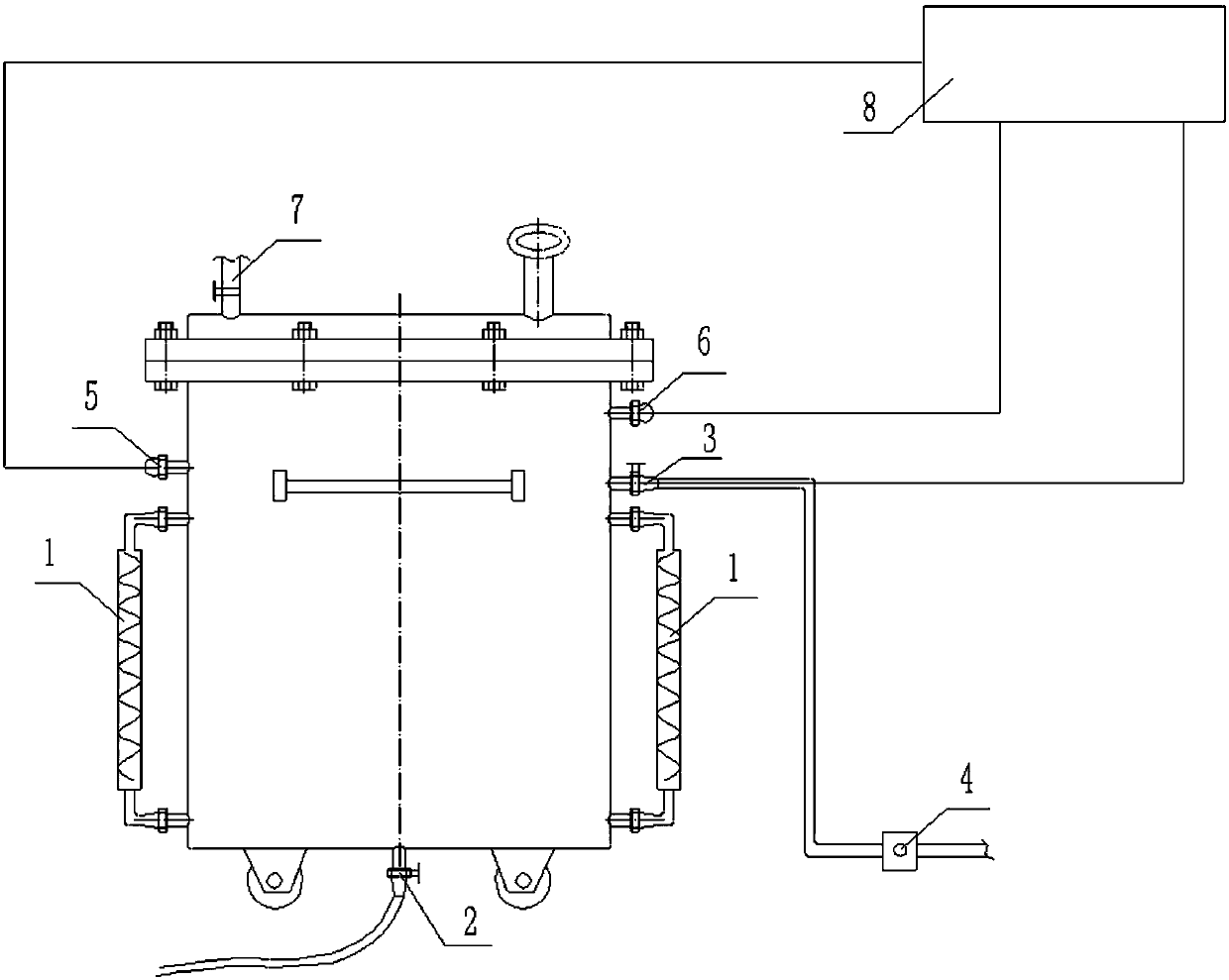
[0024] Such as figure 1 As shown, a slurry turnover tank according to an embodiment of the present invention includes a tank body, a slurry feed pipe 3 is connected to the upper part of the tank body, and a slurry discharge pipe is connected to the bottom of the tank body 2. A number of circulation pipes are evenly distributed on the outer circumference of the tank, and a pump is arranged on the circulation pipe, and the circulation pipe is vertically arranged and its upper and lower ends are...


PUM


Abstract

The invention discloses a slurry turnover tank and a method avoiding the viscosity difference of slurry in the turnover tank. The slurry turnover tank comprises a tank body. The upper portion of the tank body is connected with a slurry feeding pipe, and the bottom of the tank body is connected with a slurry discharging pipe. A plurality of circulation pipes are evenly distributed on the circumference of the outer portion of the tank body and provided with pumps. The circulation pipes are vertically arranged, and the upper ends and the lower ends of the circulation pipes communicate with the interior of the tank body. The slurry turnover tank and the method avoiding the viscosity difference of slurry in the turnover tank have the beneficial effects that up-down circulation of slurry in theturnover tank can be achieved, it is guaranteed that slurry at the top and slurry at the bottom are consistent in viscosity, and a foundation is laid for coating face density stability; bubbles can beeffectively prevented from being guided into the slurry, and the slurry state is guaranteed; and production noise can be effectively lowered through usage of screw pumps.

Description

technical field [0001] The invention relates to the technical field of turnover tanks, in particular to a slurry turnover tank and a method for solving the viscosity difference of slurry in the turnover tank. Background technique [0002] In the lithium-ion battery mixing process, after the slurry is combined, it needs to be pumped into the turnover tank first, and then discharged from the turnover tank for the coating process. When the slurry is stored in the turnover tank, although the stirring paddle in the turnover tank is stirring all the time, the slurry will settle due to the slow stirring speed, resulting in the viscosity at the bottom being higher than that at the top, and the viscosity of the slurry gradually changes during the discharging process. Small, the consistency cannot be guaranteed, resulting in unstable coating surface density. [0003] Ensuring that the upper, middle and lower parts of the slurry in the turnover tank are in the same state and the same ...

Claims


Application Information

Patent Timeline
Patent Type & Authority Applications(China)
IPC IPC(8): B65D88/54B65D90/48B65D90/18F04C2/16
CPCB65D88/64B65D90/18B65D90/48F04C2/16
Inventor 张富
Owner SHANXI CHANGZHENG POWER TECH CO LTD
Why Eureka
Try Eureka