Fan device and flue gas turbine

A fan and smoke machine technology, applied in the direction of pump devices, machines/engines, pumping devices for elastic fluids, etc., can solve the problems of high noise, affecting user experience, high energy consumption, etc., to reduce energy consumption, Improve user experience and reduce noise

Pending Publication Date: 2018-05-11
GUANGDONG MIDEA KITCHEN APPLIANCES MFG CO LTD +1
View PDF12 Cites 3 Cited by
  • Summary
  • Abstract
  • Description
  • Claims
  • Application Information

AI Technical Summary

Problems solved by technology

Since the gas is accelerated by the wind wheel and hits the side wall of the fan casing vertically, the gas is forced to flow along the pipeline by the extrusion of the gas, and finally exhausted from the fan outlet. However, this exhaust method will cause two problems: high energy consumption and noisy
Specifically, in order to achieve a large air volume, it must be achieved by increasing the speed, resulting in high energy consumption; because the gas directly hits the side wall of the housing, it will generate a large amount of additional noise, which will affect the user experience

Method used


Image

  • Fan device and flue gas turbine
  • Fan device and flue gas turbine
  • Fan device and flue gas turbine

Examples


Embodiment Construction

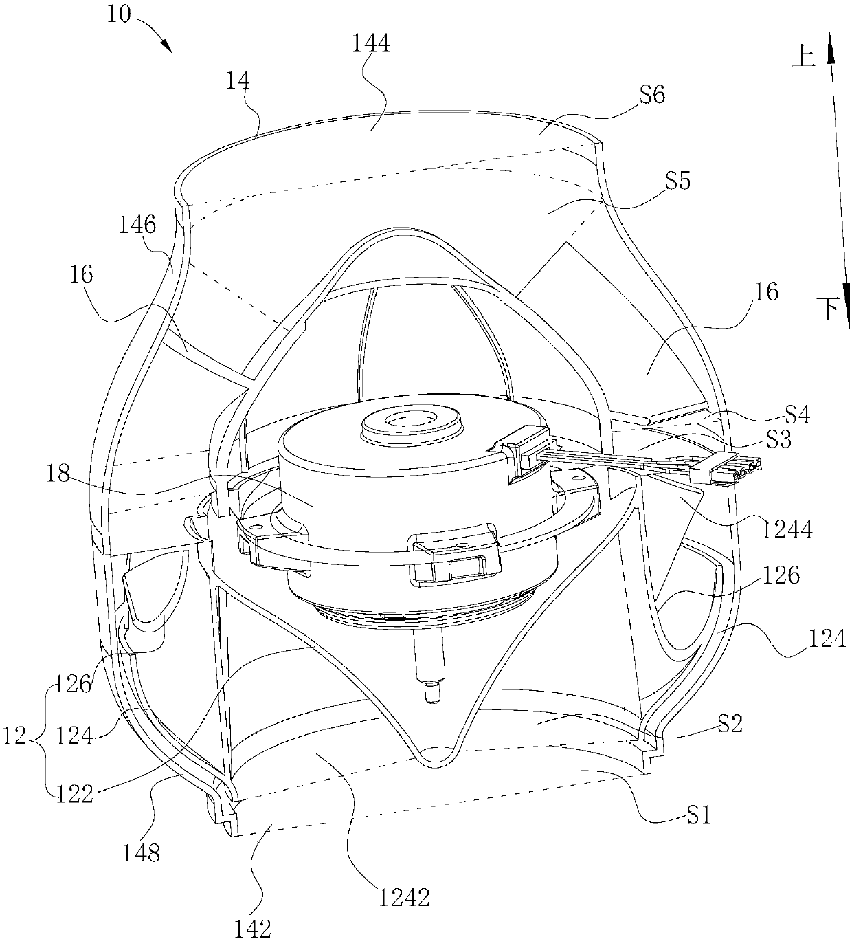
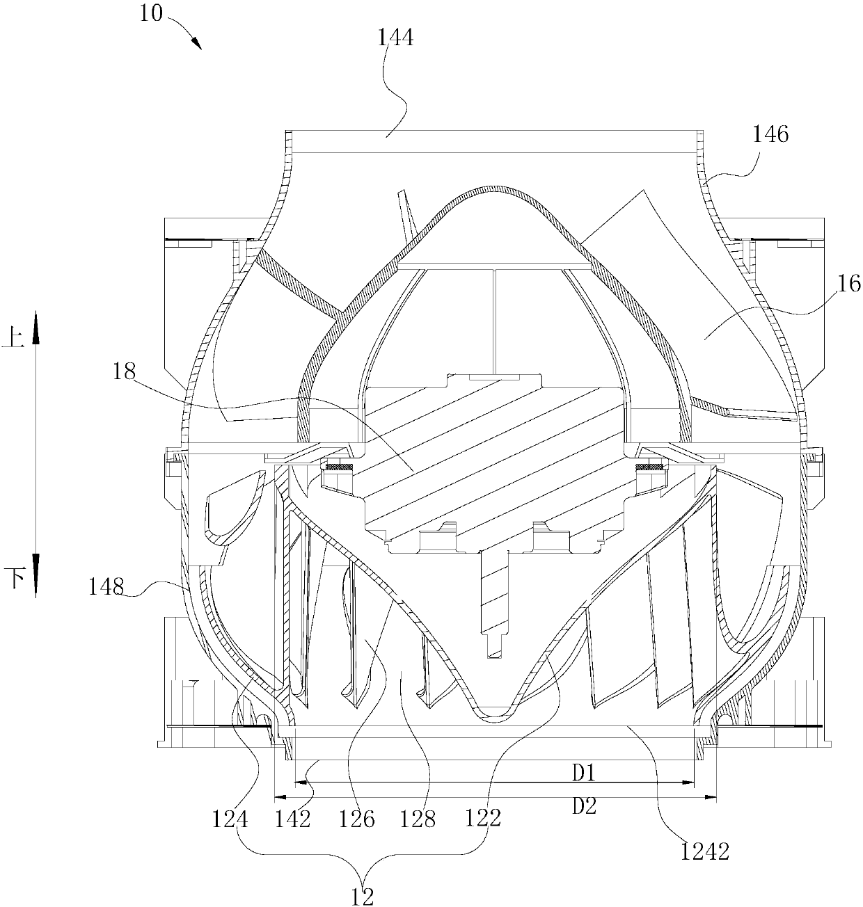
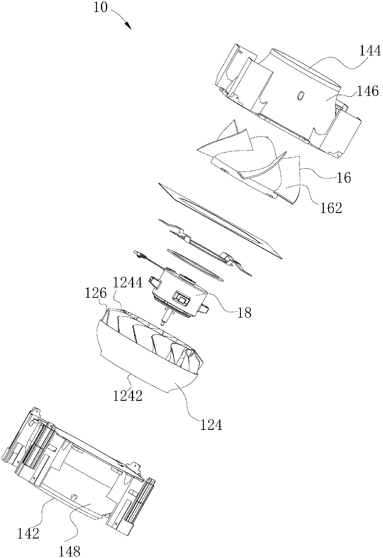
[0035] Embodiments of the present invention are described in detail below, examples of which are shown in the drawings, wherein the same or similar reference numerals denote the same or similar elements or elements having the same or similar functions throughout. The embodiments described below by referring to the figures are exemplary only for explaining the present invention and should not be construed as limiting the present invention.

[0036] In describing the present invention, it should be understood that the terms "center", "longitudinal", "transverse", "length", "width", "thickness", "upper", "lower", "front", " Orientation or position indicated by "back", "left", "right", "vertical", "horizontal", "top", "bottom", "inner", "outer", "clockwise", "counterclockwise" The relationship is based on the orientation or positional relationship shown in the drawings, and is only for the convenience of describing the present invention and simplifying the description, rather than...


PUM


Abstract

The invention discloses a fan device and a flue gas turbine. The fan device comprises a wind wheel and a shell. The wind wheel is arranged in the shell. The wind wheel comprises a hub, a wheel disc and multiple blades. The wheel disc is arranged around the hub and arranged at a certain distance from the hub. An airflow inlet is formed in the bottom of the wheel disc. An airflow outlet is formed inthe top of the wind disc. The blades are connected between the wheel disc and the hub at intervals in the peripheral direction of the hub. An air flue is formed between every two adjacent blades. Each air flue comprises a centrifugal section and a rectification section connected with the centrifugal section. The centrifugal sections communicate with the airflow inlet. The centrifugal sections areconfigured to enable the airflow entering from the airflow inlet to be centrifugally accelerated, and the rectification sections communicate with the airflow outlet and are configured to change the flowing direction of the airflow flowing out from the centrifugal sections to enable the flowing direction to be consistent with the flowing direction of the airflow entering the airflow inlet. According to the fan device, after the airflow flows to the centrifugal sections through the airflow inlet and is accelerated, the direction of the airflow flowing to the wind wheel is consistent with the direction of the airflow flowing out for the wind wheel, so that it is effectively avoided that the airflow vertically collides with the side wall of the shell after being accelerated by the wind wheel,and the noise is lowered.

Description

technical field [0001] The invention relates to the technical field of smoke machines, in particular to a fan device and a smoke machine. Background technique [0002] In the hood of the related art, the common wind wheel of the duct fan adopts the backward centrifugal wind wheel. Since the gas is accelerated by the wind wheel and hits the side wall of the fan casing vertically, the gas is forced to flow along the pipeline by the extrusion of the gas, and finally exhausted from the fan outlet. However, this exhaust method will cause two problems: high energy consumption and noisy. Specifically, in order to achieve a large air volume, the rotational speed must be increased, resulting in high energy consumption; as the gas directly hits the side wall of the casing, it will generate a large amount of additional noise, which affects user experience. Contents of the invention [0003] Embodiments of the present invention provide a blower device and a hood. [0004] The fan d...

Claims


Application Information

Patent Timeline
Patent Type & Authority Applications(China)
IPC IPC(8): F04D25/06F04D29/28F04D29/30F04D29/42F04D29/44F04D29/66
CPCF04D25/0606F04D29/281F04D29/30F04D29/4206F04D29/4213F04D29/4226F04D29/441F04D29/661
Inventor 刘伟龙陈昊蒋济武季俊生
Owner GUANGDONG MIDEA KITCHEN APPLIANCES MFG CO LTD
Why Eureka
Try Eureka