Antenna structure and wireless communication device applying antenna structure

A technology of wireless communication device and antenna structure, which is applied in the direction of antenna grounding switch structure connection, antenna grounding device, and devices that enable antennas to work in different bands at the same time, which can solve the problem of poor radiation performance of built-in antennas, easy interference with signals, and difficult Broadband design and other issues

Inactive Publication Date: 2018-05-11
SHENZHEN FUTAIHONG PRECISION IND CO LTD +1
View PDF6 Cites 5 Cited by
  • Summary
  • Abstract
  • Description
  • Claims
  • Application Information

AI Technical Summary

Problems solved by technology

However, the metal shell is easy to interfere with the signal radiated by the antenna installed in it, a...

Method used


Image

  • Antenna structure and wireless communication device applying antenna structure
  • Antenna structure and wireless communication device applying antenna structure
  • Antenna structure and wireless communication device applying antenna structure

Examples


Embodiment Construction

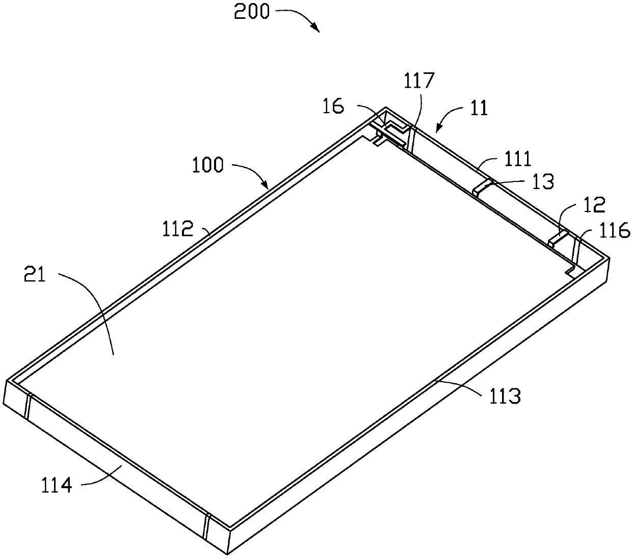
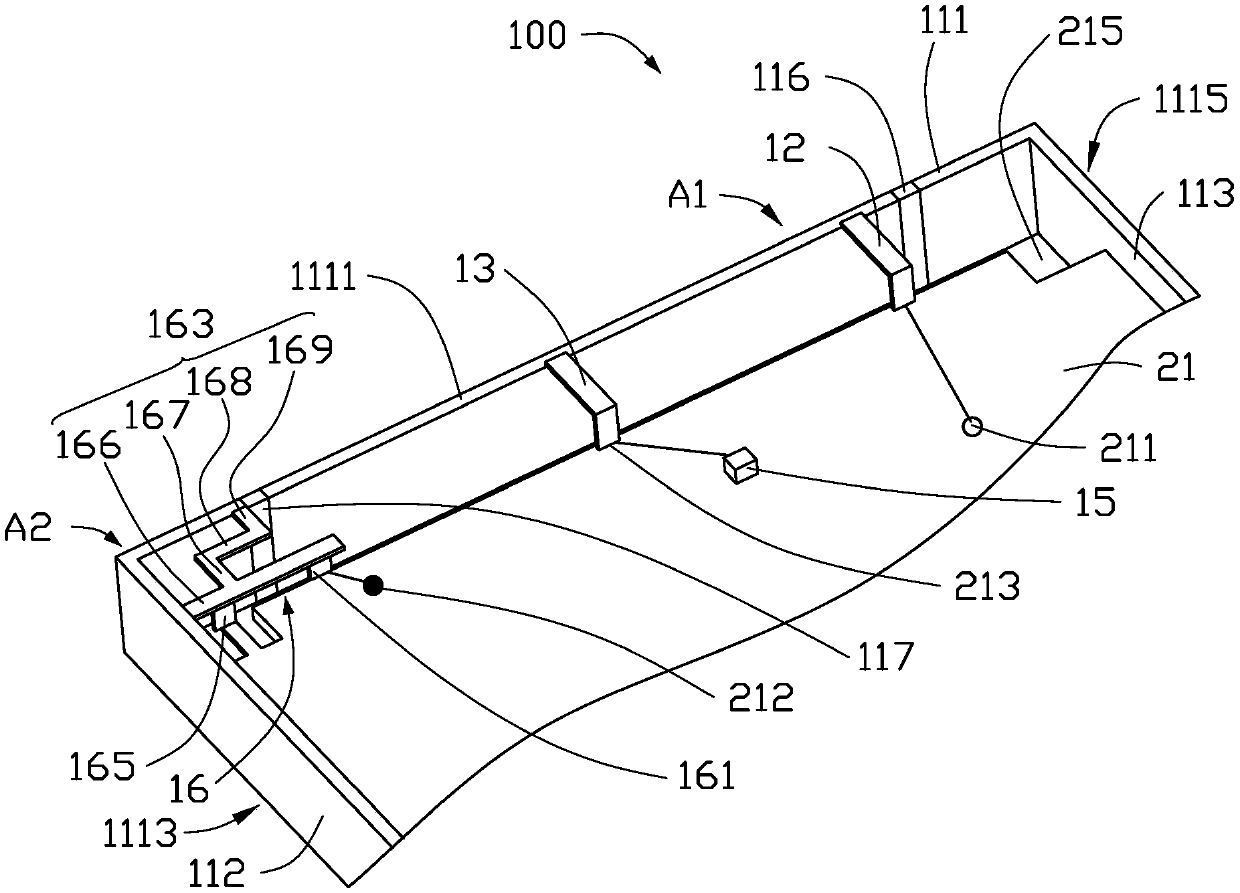
[0028] see figure 1 and figure 2 , The first preferred embodiment of the present invention provides an antenna structure 100, which is applied in wireless communication devices 200 such as mobile phones and personal digital assistants, for transmitting and receiving radio waves to transmit and exchange wireless signals.

[0029] The wireless communication device 200 also includes a substrate 21 . The substrate 21 can be made of dielectric materials such as epoxy resin fiberglass (FR4). The substrate 21 is provided with a first feeding point 211 , a second feeding point 212 and a grounding point 213 . The first feeding point 211 and the second feeding point 212 are spaced apart on the substrate 21 for feeding current to the antenna structure 100 . The grounding point 213 is disposed between the first feeding point 211 and the second feeding point 212 for providing grounding for the antenna structure 100 . A clearance area 215 is also disposed on the substrate 21 . The cle...


PUM


Abstract

The invention provides an antenna structure, which comprises a metal piece, a feed-in portion, a grounding portion and a radiator, wherein the metal piece is provided with at least one open slot, andthe at least one open slot at least divides the metal piece into a first bonding portion and a second bonding portion which are arranged at intervals; the feed-in portion feeds a current signal into the first bonding portion; the grounding portion provides grounding for the first bonding portion; the radiator is used for feeding a current signal into the second bonding portion; the first bonding portion, the feed-in portion and the grounding portion form a first antenna of the antenna structure so as to simulate a first mode to generate a radiation signal of a first frequency band, and the second bonding portion and the radiator form a second antenna of the antenna structure so as to stimulate a second mode to generate a radiation signal of a second frequency band. The antenna structure can realize the operation frequency bandwidth of multiple frequency bands and achieve requirements of LTE carrier aggregation. The invention further provides a wireless communication device applying theantenna structure.

Description

technical field [0001] The invention relates to an antenna structure and a wireless communication device using the antenna structure. Background technique [0002] With the advancement of wireless communication technology, wireless communication devices are constantly developing towards a thinner and lighter trend, and consumers have higher and higher requirements for product appearance. Since metal shells have advantages in appearance, structural strength, heat dissipation effect, etc., more and more manufacturers design wireless communication devices with metal shells to meet the needs of consumers. However, the metal shell easily interferes and shields the signal radiated by the antenna disposed therein, and it is not easy to achieve broadband design, resulting in poor radiation performance of the built-in antenna. Moreover, with the continuous development of the Long Term Evolution (Long Term Evolution, LTE) technology, the bandwidth of the antenna is continuously incre...

Claims


Application Information

Patent Timeline
IPC IPC(8): H01Q1/36H01Q1/48H01Q1/50H01Q1/22H01Q5/314H01Q5/20
CPCH01Q5/20H01Q5/314H01Q1/22H01Q1/36H01Q1/48H01Q1/50H01Q1/243H01Q9/42H01Q21/28H01Q5/35H01Q5/371H01Q5/378H01Q5/50H01Q9/30H01Q13/106
Inventor 刘耿宏
Owner SHENZHEN FUTAIHONG PRECISION IND CO LTD
Why Eureka
Try Eureka