
Motor vehicle vacuum pump

A technology of vacuum pump and motor vehicle, applied in the direction of machine/engine, pump, pump components, etc., can solve the problem of deterioration of pump power consumption, achieve the effect of improving efficiency and reducing noise emission

Inactive Publication Date: 2018-05-11
PIERBURG PUMP TECH
View PDF6 Cites 0 Cited by
  • Summary
  • Abstract
  • Description
  • Claims
  • Application Information

AI Technical Summary

Problems solved by technology

The problem arises from this that due to these measures the pump chamber is vented, whereby the power consumption of the pump is significantly worsened

Method used


Image

  • Motor vehicle vacuum pump
  • Motor vehicle vacuum pump
  • Motor vehicle vacuum pump

Examples


Embodiment Construction

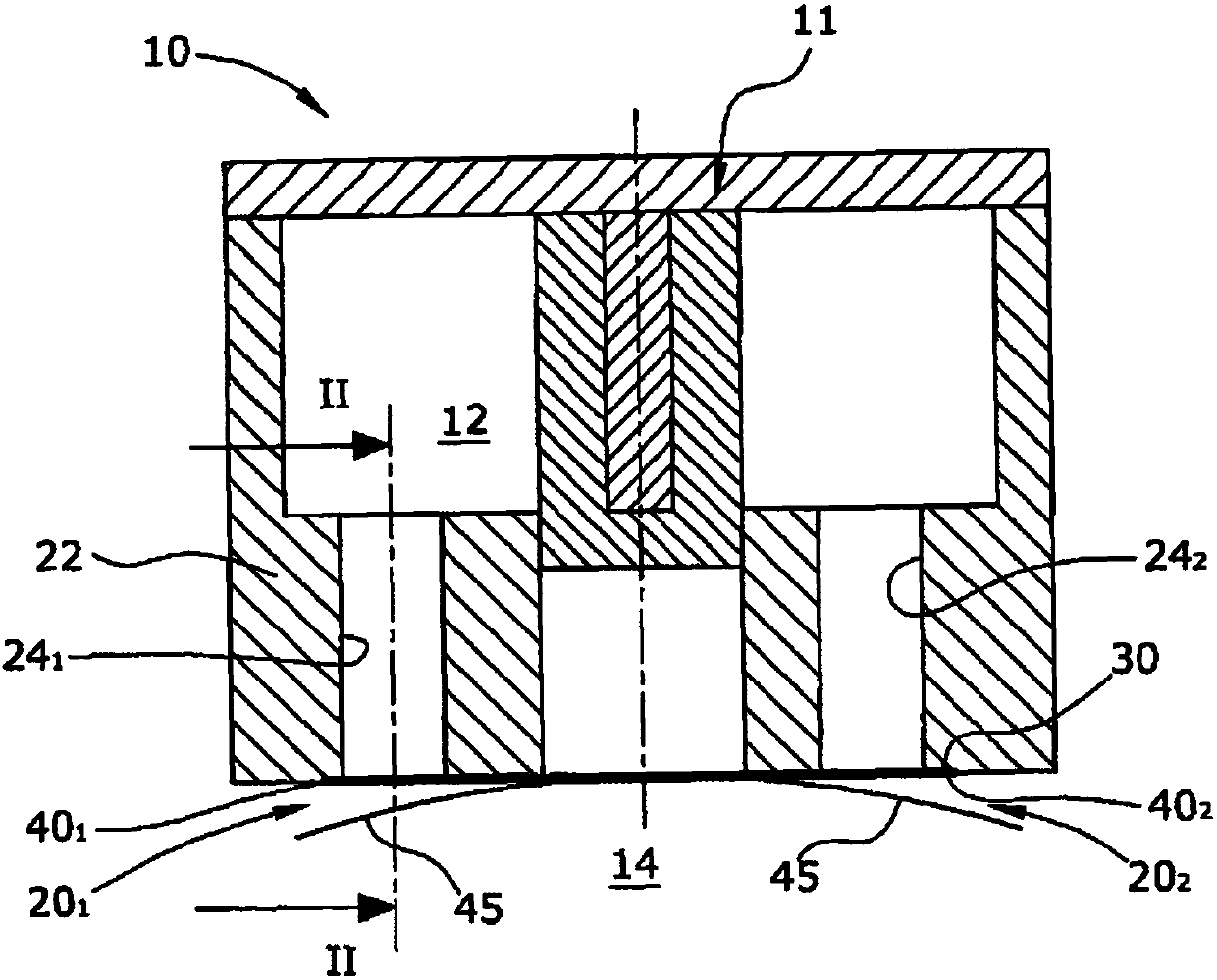
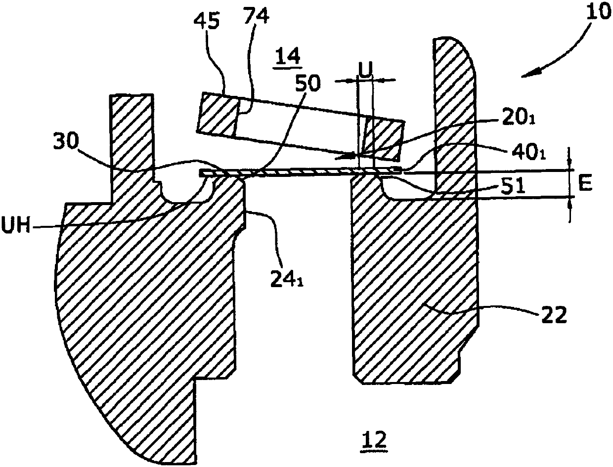
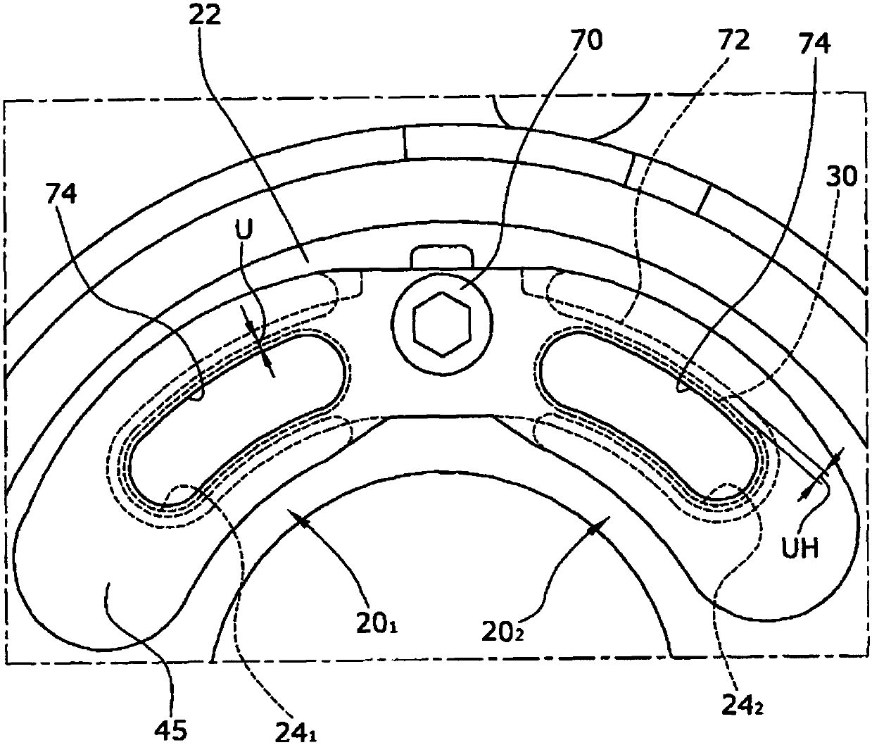
[0025] figure 1 A motor vehicle vacuum pump 10 according to the invention is shown. The vacuum pump 10 forms a pump chamber 12 in which gas is compressed by a rotating pump rotor 11 . A partition 22 separates the pump chamber 12 from the outlet chamber 14 . In the partition wall 22, a kidney-shaped valve hole 24 is designed for forward rotation 1 and kidney-shaped valve hole 24 during reverse rotation 2 . For fluid communication between the pump chamber 12 and the outlet chamber 14, the vacuum pump 10 has an outlet valve 20 designed as a check valve for forward rotation. 1 and outlet valves designed for reverse rotation of the check valve 20 2 . Outlet valve 20 1 ,20 2 With kidney-shaped leaf spring 40 as valve body 1 ,40 2 , the leaf spring closes the valve hole 24 in the closed state 1 ,twenty four 2 .

[0026] exist figure 2 The outlet valve 20 is shown by forward rotation when 1 Cutaway cutaway view. Outlet valve 20 during forward rotation 1 Made of kidne...


PUM


Abstract

The invention relates to motor vehicle vacuum pump (10), comprising a pump chamber (12), in which a pump rotor (11) rotates in a compressing manner, and an outlet chamber (14), into which the compressed gas escapes from the pump chamber (12). The vacuum pump (10) has a separating wall (22), which separates the pump chamber (12) from the outlet chamber (14), and at least one outlet valve (201, 202)in the separating wall (22), which is designed as a check valve and through which the compressed gas escapes from the pump chamber (12) into the outlet chamber (14). The outlet valve (201, 202) is formed by a valve opening (241, 242) in the separating wall (22), a valve seat (30), which is provided around the valve opening (241, 242), and a leaf spring (401, 402) as a valve body. The valve seat (30) is formed in a raised manner. The radial overlap (U) of the valve seat (30) and the leaf spring (401, 402) is less than 1.5 mm, and the radial overhang (UH) of the leaf spring (401, 402) is greater than 1.0 mm.

Description

technical field [0001] The invention relates to a motor vehicle vacuum pump having a pump chamber in which a pump rotor rotates in a sealing manner and a discharge chamber from which compressed gas is discharged into the discharge chamber. The vacuum pump has a partition wall separating the pump chamber from the outlet chamber, and at least one outlet valve is formed in the partition wall as a non-return valve through which compressed gas is expelled from the pump chamber into the outlet chamber. Background technique [0002] Motor vehicles - Vacuum pumps in motor vehicles (Kfz) independently of the operating state of the internal combustion engine generate, for example, a vacuum of 100 mbar absolute, which is required, for example, for operating pneumatic brake boosters and / or other pneumatically operated auxiliary units . [0003] In such vacuum pumps, a leaf spring is usually used as the valve body of the outlet valve due to its simple structure and high reliability, and...

Claims


Application Information

Patent Timeline
IPC IPC(8): F04C25/02F04C29/12F04C18/344
CPCF04C25/02F04C18/3441F04C29/128F04C18/00F04C29/02
Inventor S.哈默W.皮伦兹E.德斯S.索默M.J.乔布
Owner PIERBURG PUMP TECH
Learn More