Numerical control device

A numerical control device and data technology, applied in the direction of automatic control device, program control, feeding device, etc., can solve problems such as inability to perform accurate positioning, and achieve the effect of high-precision positioning control

Inactive Publication Date: 2018-05-11
DMG MORI CO LTD
View PDF1 Cites 2 Cited by
  • Summary
  • Abstract
  • Description
  • Claims
  • Application Information

AI Technical Summary

Problems solved by technology

[0017] However, in the above-mentioned conventional numerical control device, although the positioning error with respect to each feed axis, the straightness of each feed axis, and the posture error of the main shaft in three-dimensional space can be corrected, the error caused by the length of the tool cannot be corrected. The correction of the positioning error still only depends on the tool offset in the Z-axis direction corresponding to the tool length. In this regard, there is a problem that accurate positioning cannot be performed.

Method used


Image

  • Numerical control device
  • Numerical control device
  • Numerical control device

Examples


Embodiment Construction

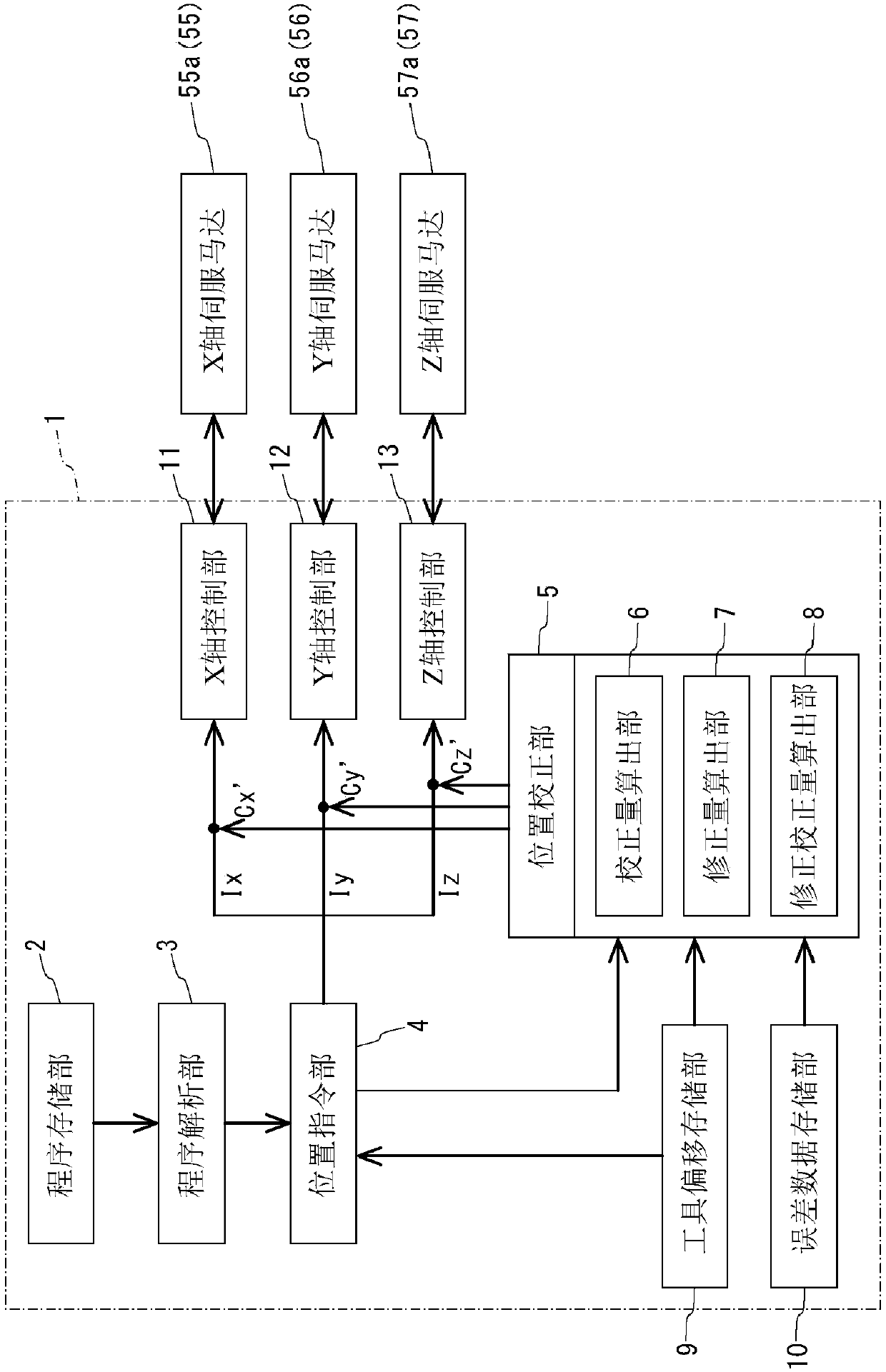
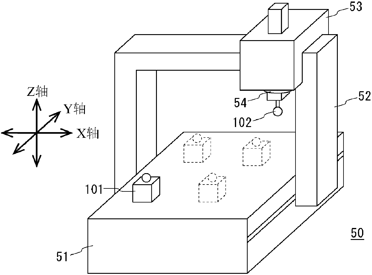
[0049] Below, while referring to the attached Figure 1 Specific embodiments of the present invention will be described. exist figure 1 A schematic configuration of a numerical control device according to an embodiment of the present invention is shown in figure 2 An example of a machine tool controlled by this numerical controller is shown in .

[0050] Such as figure 2 As shown, the machine tool 50 of this example includes a base 51 whose upper surface is a workpiece placement surface (so-called table), a door-shaped frame 52 , and a saddle 53 . The frame 52 is arranged so that its horizontal portion is above the base 51 , and its two vertical portions are respectively engaged with the side portions of the base 51 , so that the frame 52 can move in the Y-axis direction as a whole. In addition, the saddle 53 is engaged with a horizontal portion of the frame 52 and is movable in the X-axis direction along the horizontal portion. Furthermore, the saddle 53 holds the spi...


PUM


Abstract

Provided is a numerical control device with which the tip position of a tool can be positioned with high precision in a three-dimensional space. This numerical control device (1) is equipped with a position correction unit (5) and an error data storage unit (10). The error data storage unit (10) stores error data for the X-, Y-, and Z-axes, that is, data pertaining to the angular error (Eax, Eay,Eaz) around the X-axis, the angular error (Ebx, Eby, Ebz) around the Y-axis, and the angular error (Ecx, Ecy, Ecz) around the Z-axis. The position correction unit (5) calculates a revision amount (Mx,My, Mz) in accordance with the tool length, on the basis of a command position (Ix, Iy, Iz), the error data, and tool length data for the tool being used, revises a correction amount (Cx, Cy, Cz) forthe command position (Ix, Iy, Iz), and uses the revised correction amount to correct the command position (Ix, Iy, Iz).

Description

technical field [0001] The present invention relates to a numerical control of each feed axis of a machine tool including a Z axis along the axis of a main shaft, and each feed axis of an X axis and a Y axis orthogonal to the Z axis and mutually orthogonal. numerical control device. Background technique [0002] In the past, as the main cause of the motion error of the machine tool, the positioning error of each feed axis of the X-axis, Y-axis, and Z-axis, the straightness of each feed axis, and the posture error of the main shaft in the three-dimensional space were considered. As a numerical controller for compensating such a motion error, a numerical controller disclosed in Japanese Patent Application Laid-Open No. 8-152909 (Patent Document 1 below) has conventionally been proposed. [0003] As disclosed in Patent Document 1, this numerical control device is provided with: a grid point correction vector storage unit, which divides the coordinate system into grid-like regi...

Claims


Application Information

Patent Timeline
Patent Type & Authority Applications(China)
IPC IPC(8): G05B19/404B23Q15/24
CPCB23Q15/24G05B19/404G05B2219/41207B23Q2220/006B23Q2716/00B23Q2717/00G05B19/402G05B2219/36492
Inventor 井户悠下池昌広
Owner DMG MORI CO LTD
Why Eureka
Try Eureka