Glass pipe and metal pipe welding machine

A technology for glass tubes and metal tubes, applied in welding equipment, welding equipment, auxiliary welding equipment, etc., can solve the problems of inability to weld the ends of glass tubes and metal tubes, low welding efficiency, and unsatisfactory welding effects. Achieve good welding effect, high welding efficiency, and improve welding efficiency

Active Publication Date: 2018-05-15
宁波海曙洪德产品设计有限公司
View PDF7 Cites 7 Cited by
  • Summary
  • Abstract
  • Description
  • Claims
  • Application Information

AI Technical Summary

Problems solved by technology

However, this method cannot realize the welding between the end of the glass tube and the end of the metal tube, and the welding efficiency is low, and the welding effect is not ideal, so this method needs further improvement

Method used


Image

  • Glass pipe and metal pipe welding machine
  • Glass pipe and metal pipe welding machine
  • Glass pipe and metal pipe welding machine

Examples


Embodiment Construction

[0029] The present invention will be further described in detail below in conjunction with the accompanying drawings and embodiments.

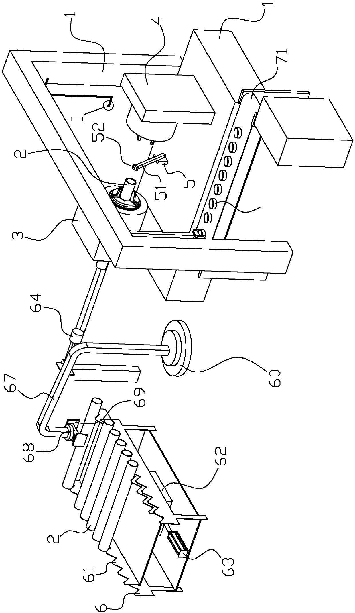
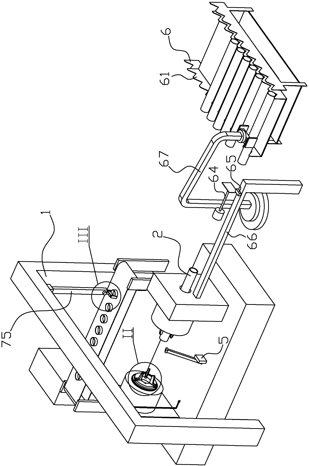
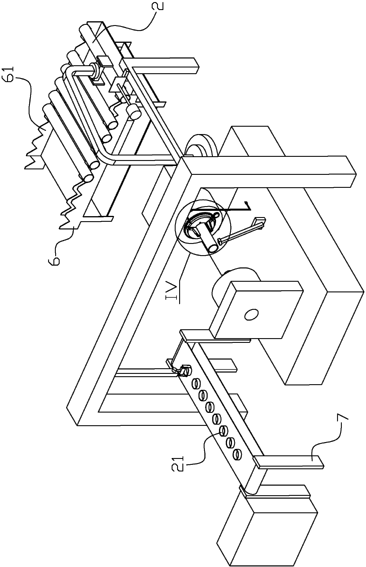
[0030] Such as Figure 1 to Figure 14 As shown, the welding machine of the glass tube and the metal tube of the present embodiment includes a frame 1, which can clamp the first clamping part of the glass tube 2, and can clamp the second clamping part of the metal tube 21, and can clamp the glass tube 2. The welding part where the tube 2 and the metal tube 21 are welded together, the welding part is arranged on the frame 1 below the end of the glass tube 2 clamped by the first clamping part, the first clamping part and the second clamping part The clamping parts are arranged oppositely and can be rotated synchronously with respect to the frame 1 on the frame 1. The second clamping part can move relative to the first clamping part to insert the metal pipe 21 into the molten metal pipe 21. On the end, one side of the frame 1 is provided with a gla...


PUM


Abstract

A glass pipe and metal pipe welding machine comprises a rack, a first clamping part, a second clamping part and a welding part. The welding part is arranged on the part, below the end portion of a glass pipe clamped by the first clamping part, of the rack, the first clamping part and the second clamping part are oppositely arranged and can be synchronously and rotationally arranged on the rack relative to the rack, and the second clamping part can move relative to the first clamping part so that a metal pipe can be connected to the end portion of the fused metal pipe in an inserted manner. Oneside of the rack is provided with a glass pipe conveying device for conveying the glass pipe to the first clamping part and a metal pipe conveying device for conveying the metal pipe to the second clamping part. The upper portion of the rack is provided with an extrusion part for extruding the end portion of the glass pipe when the glass pipe heated through the welding part rotates, and the firstclamping part, the second clamping part, the welding part, the glass pipe conveying device, the metal pipe conveying device and the extrusion part are connected with a control circuit through a line.The glass pipe and metal pipe welding machine has the beneficial effects that welding between the end portion of the glass pipe and the end portion of the metal pipe is achieved, the welding efficiency is high, and the welding effect is good.

Description

technical field [0001] The invention relates to the technical field of glass tube production, in particular to a welding machine for glass tubes and metal tubes. Background technique [0002] An existing Chinese invention patent with the patent number CN200710154507.2 titled "Metallic Glass Composite Heat Conductor Tube and Its Manufacturing Method" discloses a metal glass composite heat conduction tube arranged in an evacuated tube solar collector and a manufacturing method thereof. The metal-glass composite heat-conducting tube is formed by pouring metal tubes and glass tubes. The middle part of the metal tube is a mesh section, which is in a mesh structure. The glass tube is coated on the metal tube and exposes the two ends of the metal tube. , and includes a mesh section covered with a metal tube, one end of the metal tube is connected to the metal heat conducting tube of the vacuum tube solar heat collector, and a glass end cover is provided at the interface between the...

Claims


Application Information

Patent Timeline
Patent Type & Authority Applications(China)
IPC IPC(8): B23K31/02B23K37/053B23K37/00
CPCB23K31/02B23K37/00B23K37/0533
Inventor 胡大勋胡峰涛
Owner 宁波海曙洪德产品设计有限公司
Why Eureka
Try Eureka