
Automatic plug-in mounting device for pair-tube bases of photoelectric detectors

A technology of photodetector and plug-in device, applied in metal processing, metal processing equipment, manufacturing tools, etc., can solve problems such as low efficiency

Pending Publication Date: 2018-05-15
SHENZHEN TANDA TECH
View PDF0 Cites 3 Cited by
  • Summary
  • Abstract
  • Description
  • Claims
  • Application Information

AI Technical Summary

Problems solved by technology

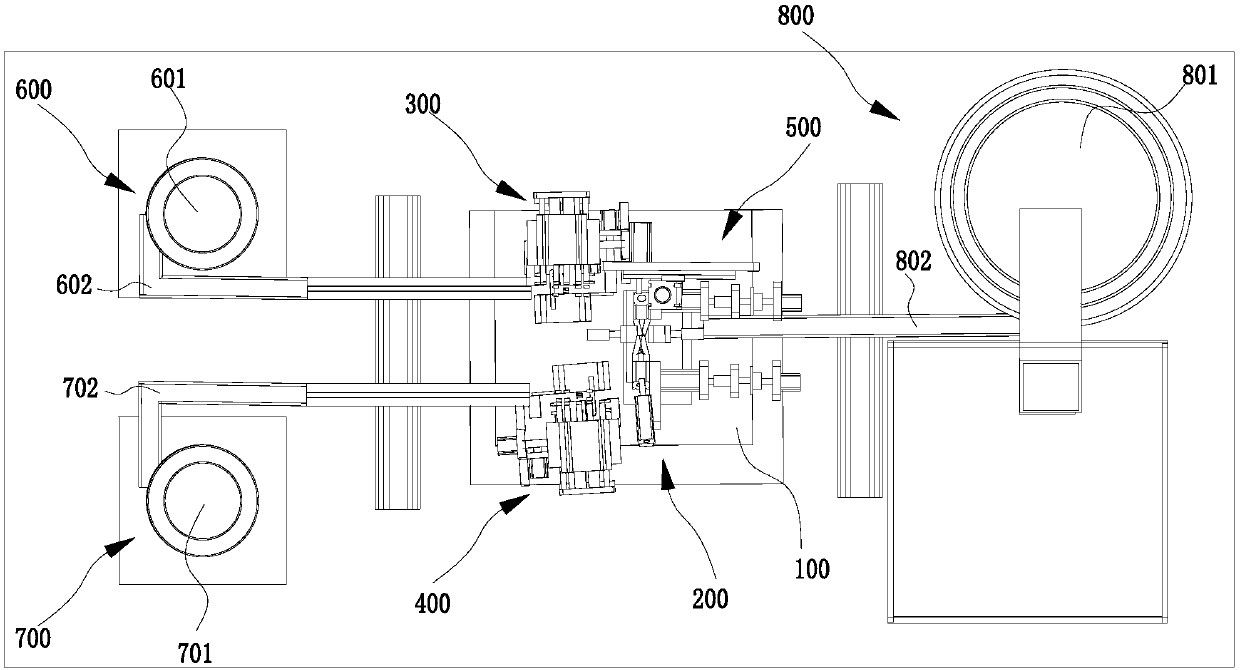
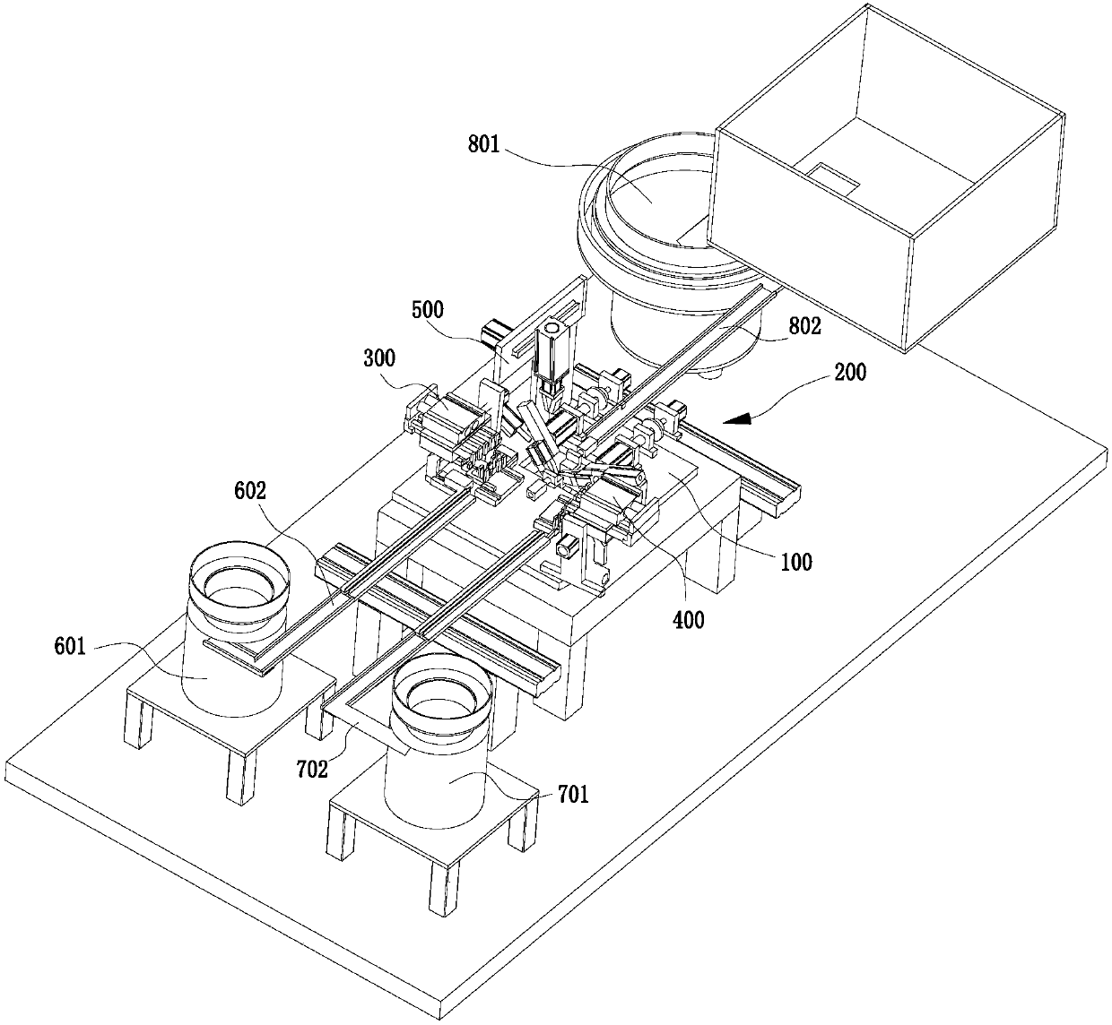
[0003] The purpose of the present invention is to provide an automatic insertion device for photodetectors to tube sockets, aiming to solve the technical problem of low efficiency caused by manually assembling diodes in the prior art

Method used


Image

  • Automatic plug-in mounting device for pair-tube bases of photoelectric detectors
  • Automatic plug-in mounting device for pair-tube bases of photoelectric detectors
  • Automatic plug-in mounting device for pair-tube bases of photoelectric detectors

Examples


Embodiment Construction

[0041] Embodiments of the present invention are described in detail below, examples of which are shown in the drawings, wherein the same or similar reference numerals designate the same or similar elements or elements having the same or similar functions throughout. The embodiments described below by referring to the figures are exemplary and are intended to explain the present invention and should not be construed as limiting the present invention.

[0042] In describing the present invention, it should be understood that the terms "length", "width", "upper", "lower", "front", "rear", "left", "right", "vertical", The orientation or positional relationship indicated by "horizontal", "top", "bottom", "inner", "outer", etc. are based on the orientation or positional relationship shown in the drawings, and are only for the convenience of describing the present invention and simplifying the description, rather than Nothing indicating or implying that a referenced device or element...


PUM


Abstract

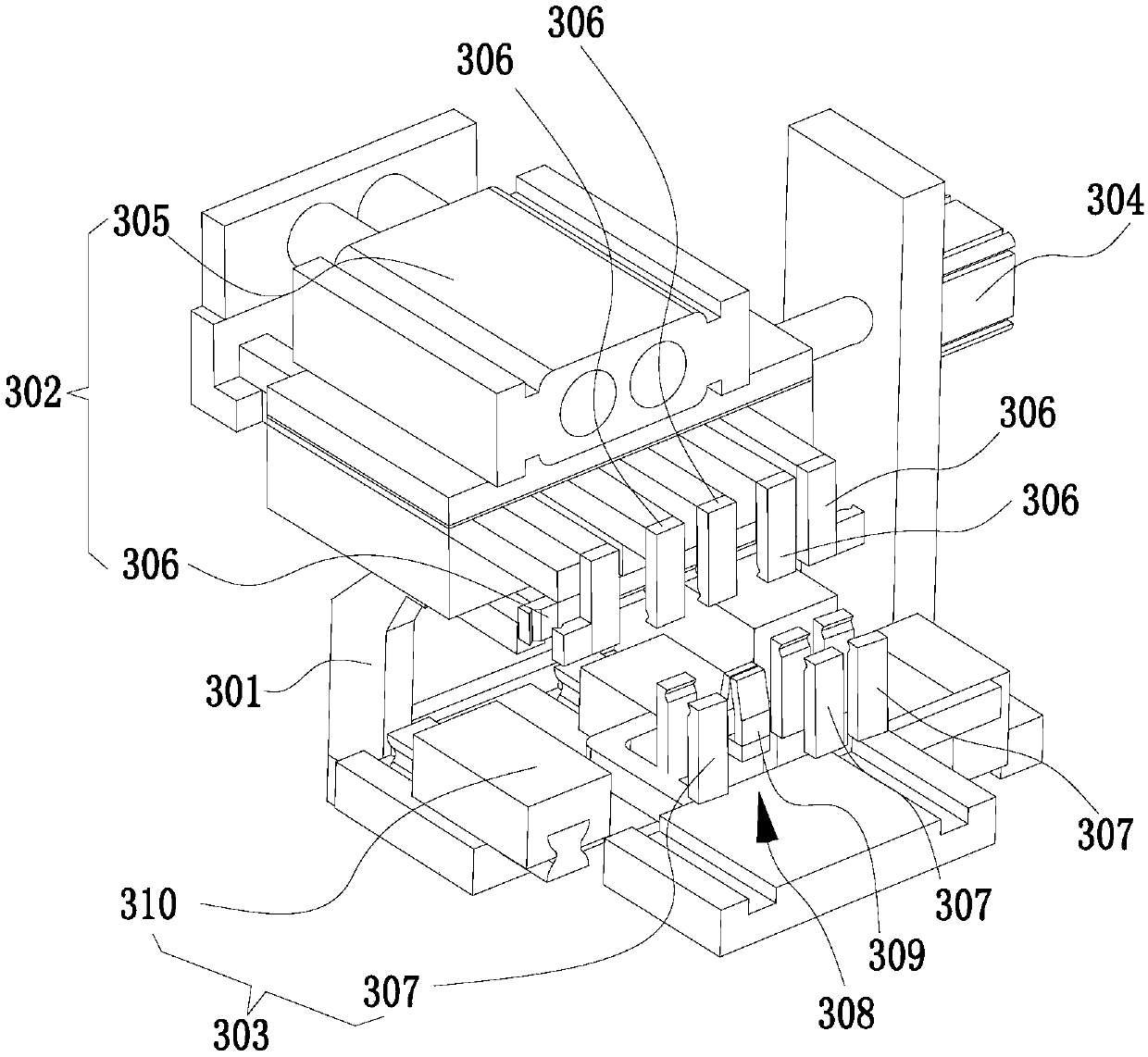
The invention relates to the technical field of automation equipment and provides an automatic plug-in mounting device for pair-tube bases of photoelectric detectors. The automatic plug-in mounting device comprises a support platform, a symmetrical plug-in mounting device, a left detection conveying device, a right detection conveying device and a transferring device, wherein emitting diodes are transmitted to the symmetrical plug-in mounting device through the left detection conveying device; in the transmitting process, the positive and negative poles of the emitting diodes are detected, andreversing is carried out so as to ensure the mounting directions of all emitting diodes at the part of the symmetrical plug-in mounting device are consistent; receiving diodes are transmitted to thepart of the symmetrical plug-in mounting device through the right detection conveying device; in the transmitting process, the positive and negative poles of the receiving diodes are detected, and reversing is carried out so as to ensure the mounting directions of all receiving diodes at the part of the symmetrical plug-in mounting device are consistent; and base bodies are transmitted to the partof the symmetrical plug-in mounting device through the transferring device, and the emitting diodes and the receiving diodes are symmetrically plugged onto the base bodies by utilizing the symmetrical plug-in mounting device. The whole process adopts automatic operation, and assembly spends short time.

Description

technical field [0001] The invention relates to the technical field of automation equipment, and in particular provides an automatic insertion device for a photoelectric detector to a tube base. Background technique [0002] The photodetector pair base includes a base body, an emitting diode and a receiving diode. During the manufacturing process, the emitting diode and the receiving diode need to be symmetrically plugged into the base body. Only when the positive and negative poles of the emitting diode and the receiving diode are aligned, the assembled pair of tube sockets is a qualified product. However, at present, most of the manual methods are used to symmetrically insert the transmitting diode and the receiving diode on the base body, and simultaneously detect whether the positive and negative poles of the transmitting diode and the receiving diode are aligned during the assembly process. In this way, the whole process takes a long time and the efficiency Low. Ther...

Claims


Application Information

Patent Timeline
IPC IPC(8): B23P19/00B23P19/027
CPCB23P19/002B23P19/027
Inventor 陈宇弘谢宗吉刘振东张高锋姚德涛
Owner SHENZHEN TANDA TECH
Learn More