Efficient numerical control vehicle clamp and clamp installation method

A car fixture, high-efficiency technology, applied in the direction of clamping, positioning devices, manufacturing tools, etc., can solve the problems of surface clamping, low surface processing quality, low efficiency, etc., achieve high surface processing quality, reduce labor intensity, and facilitate adjustment fast effect

Pending Publication Date: 2018-05-15
AVIC LIYUAN HYDRAULIC
View PDF10 Cites 5 Cited by
  • Summary
  • Abstract
  • Description
  • Claims
  • Application Information

AI Technical Summary

Problems solved by technology

Under the existing technology, the turning process of the end cap is processed on a common car, and the processing method has the following problems: 1. The clamping method of the end cap is four-claw clamping, and the clamping position is two non-hole Ts on the end cap. On the end face and the T end face with holes, since the end cover has no end face positioning (that is, the movement in the X direction of the machine tool is not restricted), and the center hole of the casting blank deviates greatly from the shape, the verticality and rotation of the processing surface of the end cover should be corrected The center is very cumbersome, and it takes 15 to 20 minutes to clamp an end cover, which is very inefficient; 2. During the processing, due to the excessive clamping force of the four claws, the surface of the product will be pinched and deformed, because The four claws are clamped to the center at the same time, which will cause the problem of convex and concave. After the processing is completed, after the four claws are loosened, the product will rebound, that is, concave and convex, and eventually the flatness cannot be guaranteed. Directly Affect surface finish quality
[0003] Therefore, the turning process of the end cover under the existing fixture and clamping method has the disadvantages of low efficiency and low surface processing quality

Method used


Image

  • Efficient numerical control vehicle clamp and clamp installation method
  • Efficient numerical control vehicle clamp and clamp installation method
  • Efficient numerical control vehicle clamp and clamp installation method

Examples


Embodiment Construction

[0036] The present invention will be further described below in conjunction with the accompanying drawings and embodiments, but not as a basis for limiting the present invention.

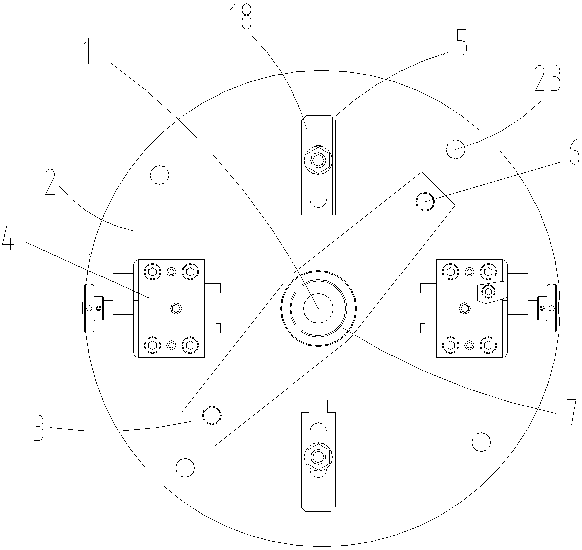
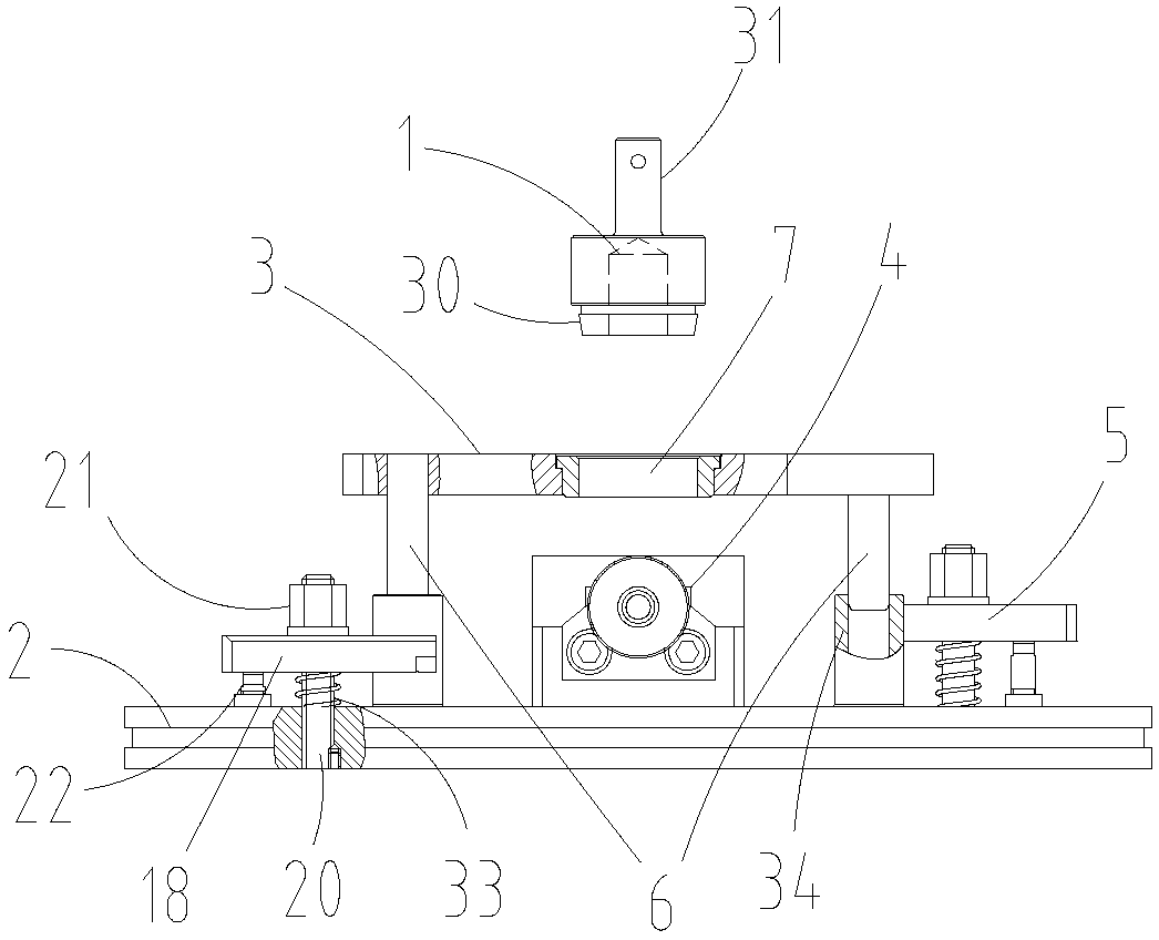
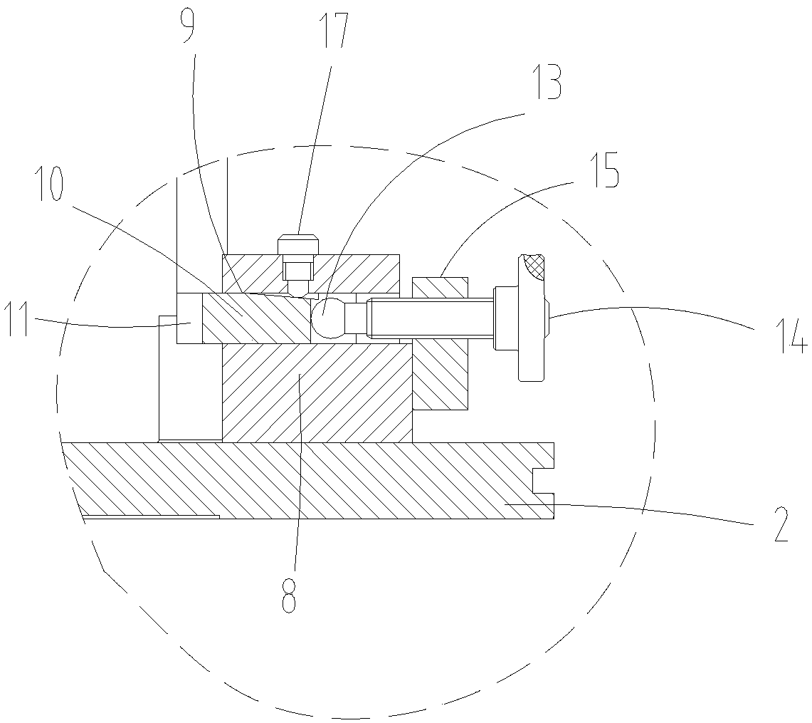
[0037] Example. A high-efficiency CNC car fixture, such as figure 1 and figure 2 As shown, it includes a calibration mandrel 1 and a faceplate 2. The faceplate 2 is provided with a mounting hole 23, a guide sleeve 34, two sets of clamping mechanisms 4 distributed symmetrically about the axis of the faceplate 1, and two sets of clamping mechanisms distributed symmetrically about the axis of the faceplate 1. Mechanism 5, a correction plate 3 is provided above the faceplate 2, and the correction plate 3 is connected with the guide sleeve 34 through the guide rod 6. The correction plate 3 is provided with a correction hole 7 coaxial with the faceplate 2, and the correction hole 7 is connected with the correction mandrel 1 fit. The guide sleeve 34 is fixedly connected with the faceplate, and the gui...


PUM


Abstract

The invention discloses an efficient numerical control vehicle clamp and a clamp installation method. The clamp comprises a correction core shaft and a face plate, the face plate is provided with a mounting hole, a guide sleeve, two clamping mechanisms and two pressing mechanisms, wherein the clamping mechanisms are distributed in axis symmetry about the face plate, the pressing mechanisms are distributed in axis symmetry about the face plate, a correction plate is arranged above the face plate and is connected with the guide sleeve through a guide rod, the correction plate is provided with acorrection hole coaxial to the face plate, and the correction hole coincides with the correction core shaft; the clamping mechanisms comprise fixing blocks connected with the face plate, each fixing block is provided with a guide hole, the guide hole is internally provided with a movable block, protrusions are arranged at the two sides of the end, close to the core part of the face plate, of the movable block, a through hole is formed in the end, away from the core part of the face plate, of the movable block and is internally provided with a ball head, and a screw is connected to the ball head and penetrates through one side of the movable block and is connected with the fixing block through a supporting plate. A machining tool for an end cover vehicle has the advantages of being high inefficiency and high in surface machining quality.

Description

technical field [0001] The invention belongs to the field of end cover clamps of A10V series hydraulic pumps, and in particular relates to a high-efficiency numerical control vehicle clamp and a clamping method. Background technique [0002] Such as Figure 6 and Figure 7 As shown, the end cover of the A10V series hydraulic pump (referred to as the end cover for convenience) has two T end faces with holes, two T end faces without holes, a blank hole coaxial with the end cover, and a flow channel inlet. and a runner outlet. In the processing process of the end cover, the turning process is an important process in the whole process route, including processing steps such as splitting the end surface, turning the step surface, digging the ring groove, and drilling and boring. This process has strict requirements on parallelism, flatness and coaxiality, etc., and the processing accuracy is high. Under the existing technology, the turning process of the end cap is processed on...

Claims


Application Information

Patent Timeline
Patent Type & Authority Applications(China)
IPC IPC(8): B23Q3/06
CPCB23Q3/06
Inventor 罗亚飞刘培云蒋丹陈薪竹倪玲卜艳新
Owner AVIC LIYUAN HYDRAULIC
Why Eureka
Try Eureka