Lathe pneumatic fixture

A pneumatic clamp and lathe technology, applied in the field of machinery, can solve the problems of small clamping range, cumbersome operation process, and failure to clamp, etc., and achieve the effect of wide application range, convenient clamping and good clamping effect

Inactive Publication Date: 2018-05-15
浙江升宏机械有限公司
View PDF10 Cites 10 Cited by
  • Summary
  • Abstract
  • Description
  • Claims
  • Application Information

AI Technical Summary

Problems solved by technology

Obviously, the operation process is cumbersome. When the length of the workpiece to be processed is long (exceeding the maximum distance between the claw and the template), it cannot be clamped, and the clamping range is small

Method used


Image

  • Lathe pneumatic fixture

Examples


Embodiment Construction

[0020] The following are specific embodiments of the present invention and in conjunction with the accompanying drawings, the technical solutions of the present invention are further described, but the present invention is not limited to these embodiments.

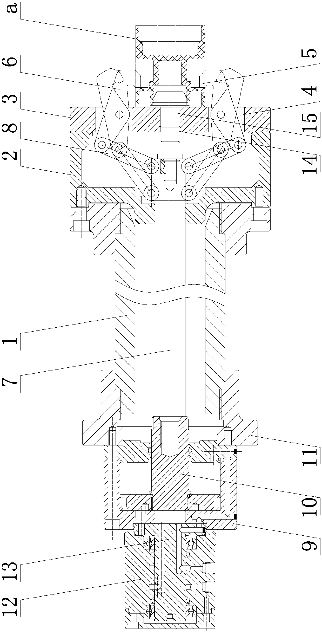
[0021] Such as figure 1 The lathe pneumatic clamp shown is set on the lathe spindle 1 with a shaft hole inside, and includes a clamp body 2 fixed on the front end of the lathe spindle 1. The clamp body 2 has a cavity concave from front to rear, and the clamp body 2 The front end is also provided with a support plate 3 for supporting the workpiece a. The support plate 3 has a number of piercing holes 4 evenly distributed along the central axis of the lathe spindle 1, and each piercing hole 4 is hinged with a belt clamping part 5 The jaws 6 are evenly distributed along the central axis of the lathe spindle 1, and the cavity is provided with a driving assembly for simultaneously driving the jaws 6 to swing around the hinge po...


PUM


Abstract

The invention provides a lathe pneumatic fixture, belongs to the technical field of machinery and solves the problem that an existing lathe pneumatic fixture is complex to operate and has poor clamping effect. The lathe pneumatic fixture arranged on a lathe spindle having a spindle hole inside and comprises a fixture body fixed to the front end of the lathe spindle, the fixture body has a cavity that is recessed from front to rear, the front end of the fixture body is also provided with a support plate for supporting a workpiece, the support plate is provided with a plurality of outgoing holesevenly distributed along the axis of the lathe spindle, a jaw having a clamping portion is hinged in each outgoing hole, the jaws are evenly distributed along the axis of the lathe spindle, and a driving component to simultaneously drive the jaws to rock around hinging points is arranged in the cavity. The lathe pneumatic fixture has the advantages of wide clamping range, good clamping effect, good clamping convenience and the like.

Description

technical field [0001] The invention belongs to the technical field of machinery and relates to a pneumatic clamp for a lathe. Background technique [0002] In the process of modern industrial production, fixtures have been widely used in lathe processing. When clamping the workpiece, if the fixture cannot fix the workpiece well, it will cause problems in the quality of the product, and the size is prone to deviation. , The accuracy and precision of processing cannot be well guaranteed, resulting in low production efficiency and the pass rate of workpiece products, which greatly reduces production efficiency and is not conducive to production. [0003] For example, a Chinese patent discloses a pneumatic rotary fixture for a lathe [authorized announcement number is CN203542166U], which includes a fixture support seat, which has two layers, the cross section of the fixture support seat is I-shaped, and the center of the lower layer of the fixture support seat is provided with ...

Claims


Application Information

Patent Timeline
Patent Type & Authority Applications(China)
IPC IPC(8): B23Q3/12
CPCB23Q3/12B23Q2703/04
Inventor 杨冬夫
Owner 浙江升宏机械有限公司
Why Eureka
Try Eureka