


Quick Research
Generate reliable direction feasibility study reports for your R&D in just a few steps.

Technical Q&A
Discover and master advanced knowledge NOW. Basics, ideas, possibilities, all at once.

Find Solutions
As an expert in R&D theories, this can generate solutions to your technical problems instantly.

Evaluate Feasibility
Analyze your overall solution with one click, know your potential R&D risks in advance.

Monitor Landscape
Get weekly tech updates, stay abreast of the latest tech innovations and key insights.
Chip polishing device for data cable manufacturing factory
A polishing device and a technology of a manufacturing plant, which are applied in the direction of manufacturing tools, grinding drive devices, grinding/polishing equipment, etc., can solve the problems of poor polishing effect and low polishing efficiency, and achieve the effect of reducing workload and improving work efficiency
- Summary
- Abstract
- Description
- Claims
- Application Information
AI Technical Summary
Problems solved by technology
Method used
Image

Examples
Embodiment 1
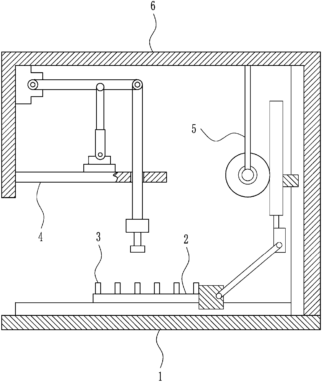
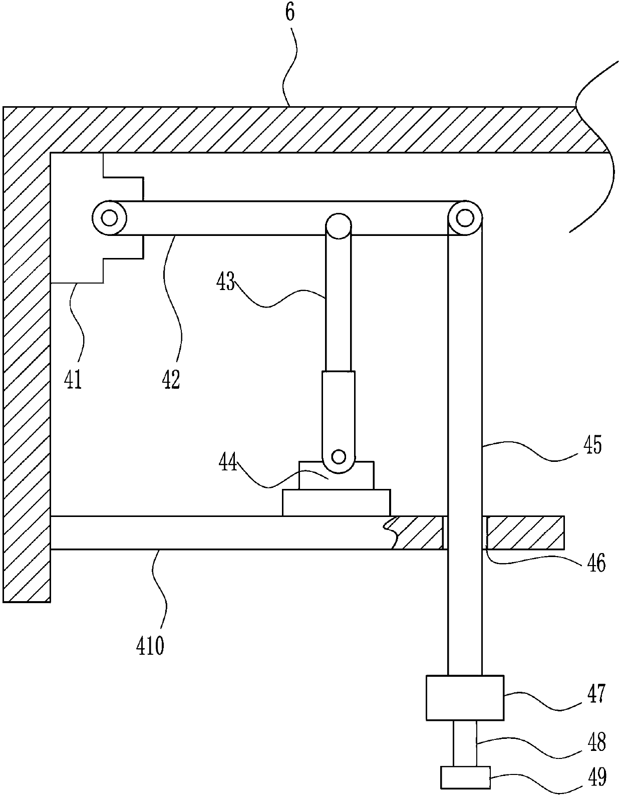
[0028] A chip polishing device for a data line manufacturing plant, such as Figure 1-5 As shown, it includes a bottom plate 1, a storage box 2, a baffle plate 3, a polishing mechanism 4, a left and right moving mechanism 5 and a mounting frame 6; the mounting frame 6 is fixed on the top of the bottom plate 1; Between the bottom plate 1, it is used to adjust the horizontal position of the chip; the storage box 2 is fixedly connected to the output end of the left and right moving mechanism 5, and the baffle plate 3 is fixedly connected to the top of the storage box 2 at equal intervals; the polishing mechanism 4 is fixedly connected to the inner wall of the installation frame 6 , and the output end of the polishing mechanism 4 is located above the placement box 2 for polishing the chip.
Embodiment 2
[0030] A chip polishing device for a data line manufacturing plant, such as Figure 1-5 As shown, it includes a bottom plate 1, a storage box 2, a baffle plate 3, a polishing mechanism 4, a left and right moving mechanism 5 and a mounting frame 6; the mounting frame 6 is fixed on the top of the bottom plate 1; Between the bottom plate 1, it is used to adjust the horizontal position of the chip; the storage box 2 is fixedly connected to the output end of the left and right moving mechanism 5, and the baffle plate 3 is fixedly connected to the top of the storage box 2 at equal intervals; the polishing mechanism 4 is fixedly connected to the inner wall of the installation frame 6 , and the output end of the polishing mechanism 4 is located above the placement box 2 for polishing the chip.
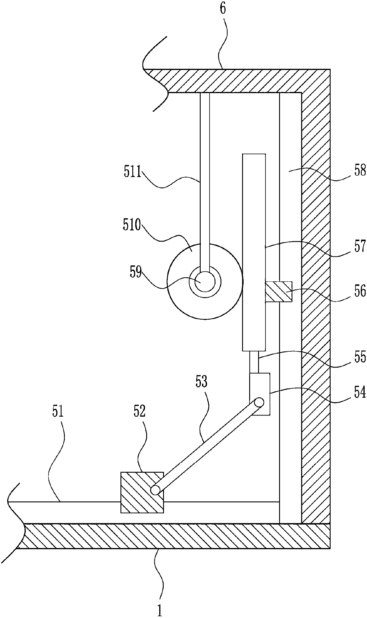
[0031]The left and right moving mechanism 5 includes a first slide rail 51, a first slide block 52, a connecting rod 53, a fixed block 54, a first pole 55, a second slide block 56, a rack 57, ...
Embodiment 3
[0033] A chip polishing device for a data line manufacturing plant, such as Figure 1-5 As shown, it includes a bottom plate 1, a storage box 2, a baffle plate 3, a polishing mechanism 4, a left and right moving mechanism 5 and a mounting frame 6; the mounting frame 6 is fixed on the top of the bottom plate 1; Between the bottom plate 1, it is used to adjust the horizontal position of the chip; the storage box 2 is fixedly connected to the output end of the left and right moving mechanism 5, and the baffle plate 3 is fixedly connected to the top of the storage box 2 at equal intervals; the polishing mechanism 4 is fixedly connected to the inner wall of the installation frame 6 , and the output end of the polishing mechanism 4 is located above the placement box 2 for polishing the chip.
[0034] The left and right moving mechanism 5 includes a first slide rail 51, a first slide block 52, a connecting rod 53, a fixed block 54, a first pole 55, a second slide block 56, a rack 57,...
PUM
 Abstract
Description
Claims
Application Information
 - R&D Engineer
- R&D Manager
- IP Professional
- Industry Leading Data Capabilities
- Powerful AI technology
- Patent DNA Extraction
Browse by: Latest US Patents, China's latest patents, Technical Efficacy Thesaurus, Application Domain, Technology Topic, Popular Technical Reports.
© 2024 PatSnap. All rights reserved.Legal|Privacy policy|Modern Slavery Act Transparency Statement|Sitemap|About US| Contact US: help@patsnap.com