Clamping head structure used for industrial robot

A technology of industrial robots and base plates, applied in the direction of chucks, manipulators, manufacturing tools, etc., can solve the problems of inconvenient disassembly and maintenance of the structure of the chucking head, inconvenient use of various workpieces, and easy side sliding of the workpieces, so as to achieve convenient installation and push. Rod and fixed block, simple structure, easy to disperse effect

Inactive Publication Date: 2018-05-15
GUANGXI RUIKE IND ROBOT CO LTD
View PDF5 Cites 15 Cited by
  • Summary
  • Abstract
  • Description
  • Claims
  • Application Information

AI Technical Summary

Problems solved by technology

[0003] The gripping head structure of the existing industrial robots still has certain defects in use. Although the existing gripping head structure can replace the human hand to grip the workpiece and process the workpiece, but because the tip of the gripping claw on the gripping head It has an arc-shaped structure. Some workpieces are more precise and need to be gripped by the tip. Some workpieces are prone to sideways slipping due to the contact between the tip and the workpiece due to their large volume. It is inconvenient to disassemble and repair, which brings inconvenience to use

Method used


Image

  • Clamping head structure used for industrial robot
  • Clamping head structure used for industrial robot
  • Clamping head structure used for industrial robot

Examples


Embodiment 1

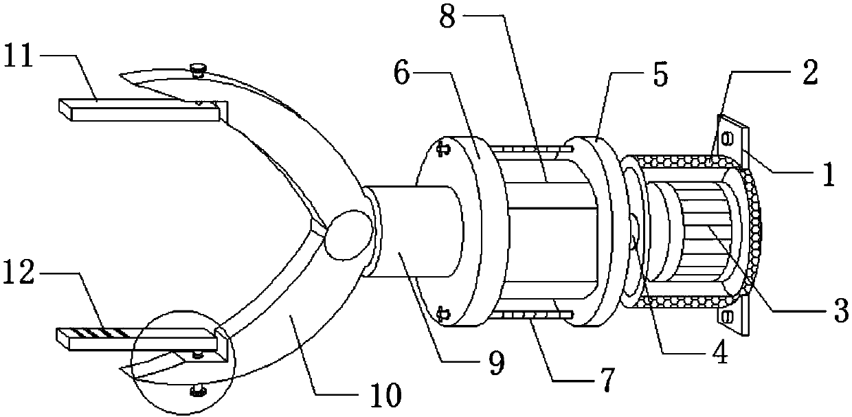
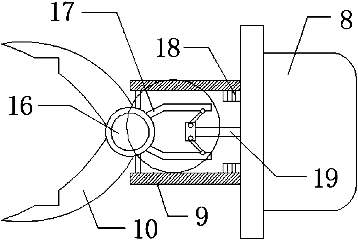
[0023] see Figure 1-4 As shown, a clamping head structure for an industrial robot includes a mounting plate 1 and a clamping claw 10. The mounting plate 1 is the connecting part of the device installed on the body of the industrial robot. A heat dissipation cover 2 is provided on one side of the mounting plate 1. , the motor 3 is installed inside the cooling cover 2, the heat generated by the motor 3 is dissipated from the cooling cover 2, the top of the motor 3 is provided with a rotating rod 4, and one end of the rotating rod 4 is provided with a base plate 5, and the top of the base plate 5 is installed with a hydraulic pressure The pump 8, the top of the hydraulic pump 8 is provided with a top plate 6, two screw rods 7 are installed between the bottom plate 5 and the top plate 6, a sleeve 9 is installed on one side of the top plate 6, a threaded joint 18 is provided at one end of the sleeve 9, and the other end of the sleeve 9 One end is provided with a turntable 16, and ...

Embodiment 2

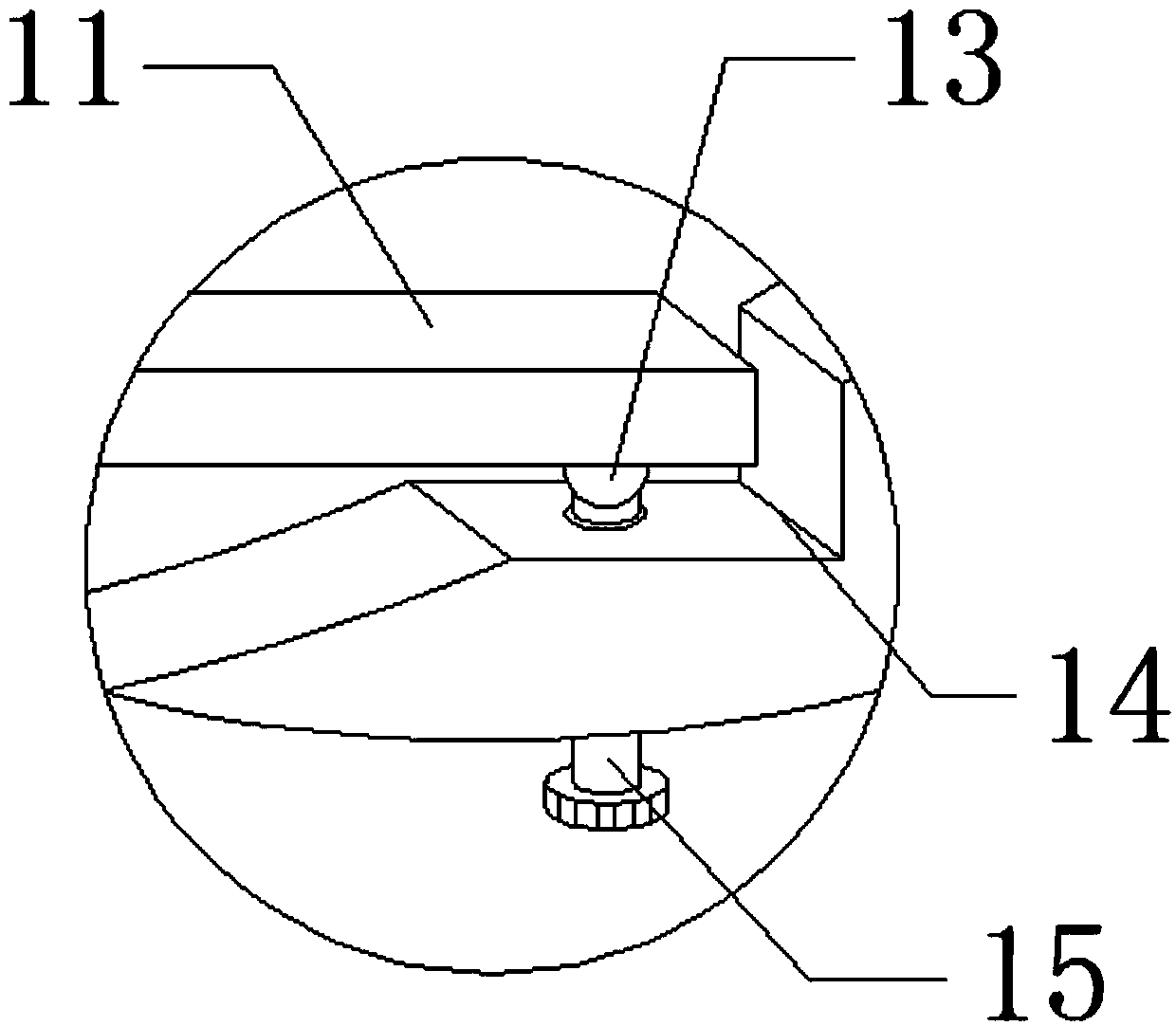
[0025] In addition, refer to Figure 1-4 , different from the above-mentioned embodiment 1, the movable rod 11 is provided with several rubber strips 12 at the end far away from the clamping jaw 10, and the two groups of rubber strips 12 are arranged symmetrically, so that the movable rod 11 can be used to clamp large volume the workpiece, and the rubber strip 12 increases the friction between the movable rod 11 and the workpiece to prevent the workpiece from falling. Rotate the connection, so that the adjusting bolt 15 can be rotated from the outside of the clamping claw 10 to rotate the movable rod 11 to a position perpendicular to the clamping claw 10, and the tip of the clamping claw 10 is used for workpiece clamping, and the two ends of the connecting rod 21 Rotating shafts 22 are arranged at both ends, and the connecting rod 21 is rotationally connected with the fixed block 20 and the control handle 17 through the rotating shaft 22, so that the connecting rod 21 can be d...


PUM


Abstract

The invention discloses a clamping head structure used for an industrial robot. The clamping head structure includes a mounting plate, a heat dissipation shield, a motor, a rotating rod, a baseplate,a top plate, screw rods, a hydraulic pump, a sleeving pipe, a clamping claw, movable rods, a rubber strip, a joint ball, a groove, an adjusting bolt, a turntable, a control handle, a threaded connector, a push rod, a fixing block, a connecting rod and a rotating shaft. The clamping head structure has the advantages that by forming the groove in the end, close to a claw tip, of the clamping claw, the two parallel movable rods are installed in the groove, and through the joint ball, the movable rods are connected with the adjusting bolt; the movable rods can be rotated through the adjusting bolt; when a clamping head is used for clamping a three-dimensional workpiece with large thickness, the movable rods can be rotated to the positions where the movable rods are parallel to the clamping claw, and therefore a sideslip problem can be effectively prevented from occurring on the tip part of the clamping claw and the workpiece when the clamping claw is used for clamping. When the tip part needs to be used for clamping, the movable rods are rotated to the positions where the movable rods are perpendicular to the clamping claw through the adjusting bolt. The clamping head structure has theadvantages of being convenient to adjust for clamping, detach and install.

Description

technical field [0001] The invention relates to a gripping head structure, in particular to a gripping head structure for industrial robots, and belongs to the technical field of industrial robot accessories. Background technique [0002] An industrial robot is a multi-joint manipulator or multi-degree-of-freedom robot for the industrial field. It is a machine device that performs work automatically. It relies on its own power and control capabilities to achieve various functions. An industrial robot consists of a main body, a drive system and a control The system consists of three basic parts. The main body is the base and the actuator, including the arm, wrist and hand, and some robots also have a walking mechanism. [0003] The gripping head structure of the existing industrial robots still has certain defects in use. Although the existing gripping head structure can replace the human hand to grip the workpiece and process the workpiece, but because the tip of the grippi...

Claims


Application Information

Patent Timeline
Patent Type & Authority Applications(China)
IPC IPC(8): B25J15/00B25J15/08B25J19/00
CPCB25J15/00B25J15/08B25J19/0054
Inventor 黄庚保
Owner GUANGXI RUIKE IND ROBOT CO LTD
Why Eureka
Try Eureka