Sewage pipeline cleaning device

A technology for cleaning devices and sewage pipes, applied to water supply devices, cleaning sewer pipes, waterway systems, etc., can solve problems such as difficult work, secondary pollution, difficult long-term operation, etc., to avoid difficult cleaning and efficient cleaning Effect

Inactive Publication Date: 2018-05-15
张桂华
View PDF7 Cites 4 Cited by
  • Summary
  • Abstract
  • Description
  • Claims
  • Application Information

AI Technical Summary

Problems solved by technology

Such a small pipeline dredging cannot be operated manually. The existing sedimentation sludge recovery device in the drainage pipeline is that the staff holds the suction hose nozzle connected to the recovery tank equipped with an air suction pump on the ground and enters the drainage pipeline to remove the sediment. The sludge is recovered from the suction hose nozzle to the recovery tank on the ground; because the working environment in the drainage pipe is poor and emits a strong odor, it is difficult to work for a long time and the work efficiency is low. In the knot state, it is still difficult to suck and recover from the hose nozzle only by suction, and it is impossible to clean up all the settled sludge from the sludge in the drainage pipe
Although there is a desilting device currently being studied, it requires a large amount of water and is not thoroughly cleaned, and many people are required to coordinate operations during work, which is difficult to work, and after cleaning, the desilting facilities are stained Full of sludge, it is easy to cause secondary pollution, so pipeline dredging has always been a problem

Method used


Image

  • Sewage pipeline cleaning device
  • Sewage pipeline cleaning device
  • Sewage pipeline cleaning device

Examples


Embodiment 1

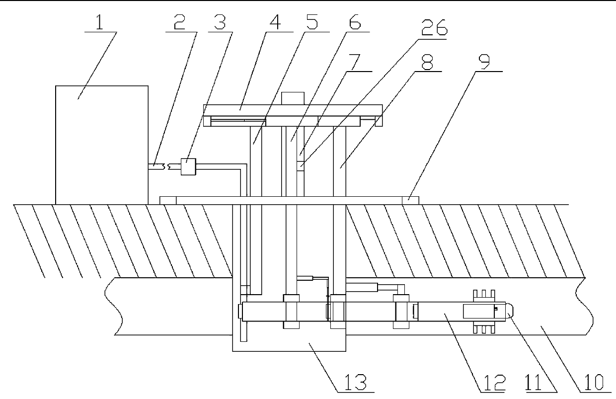
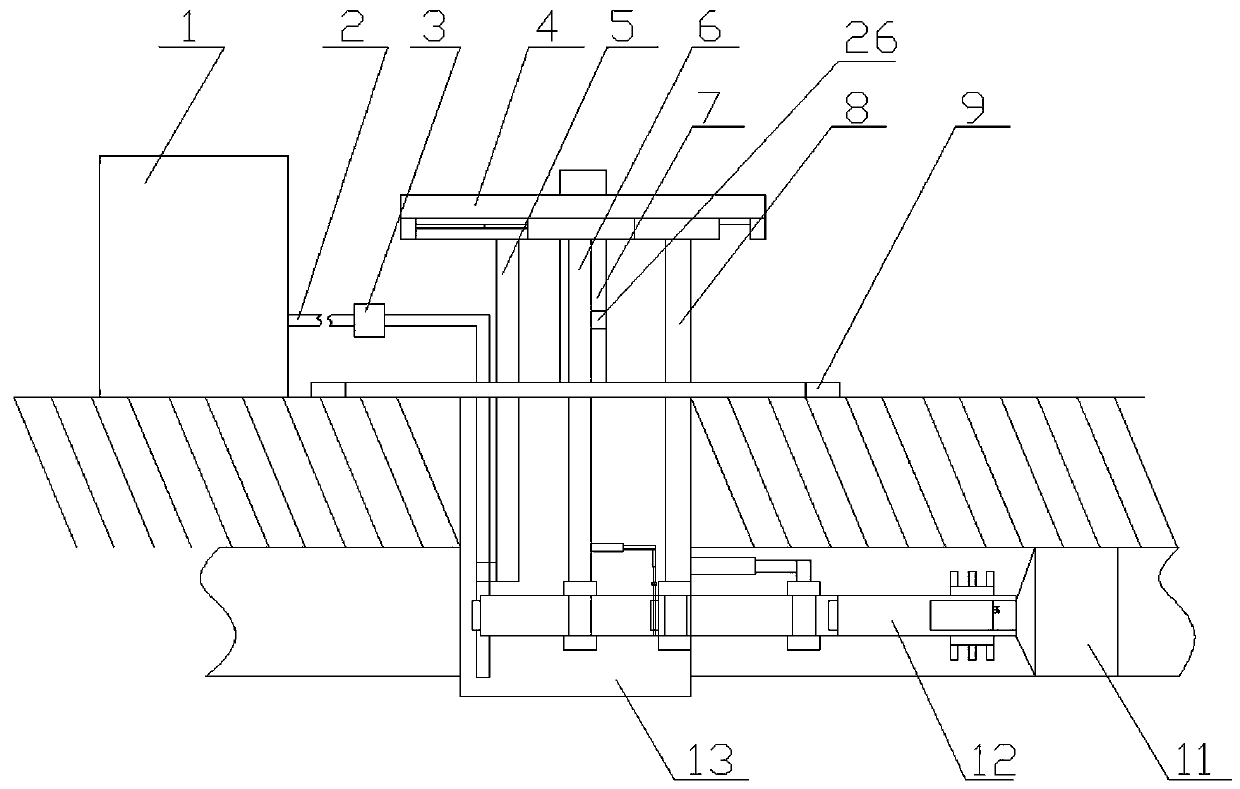
[0050] A device for cleaning sewage pipes, comprising a support mechanism arranged on the ground of a shaft 13, a dredging mechanism arranged on the support mechanism for cleaning sludge, a propulsion mechanism arranged on the support mechanism, and a propulsion mechanism arranged on the A collection mechanism for collecting mud on the propulsion mechanism, a disassembly mechanism arranged on the support mechanism for matching with the propulsion mechanism, and a disassembly mechanism arranged on the support mechanism for controlling the support mechanism, The control mechanism that cooperates with the dredging mechanism, the propulsion mechanism, the collection mechanism and the disassembly mechanism;

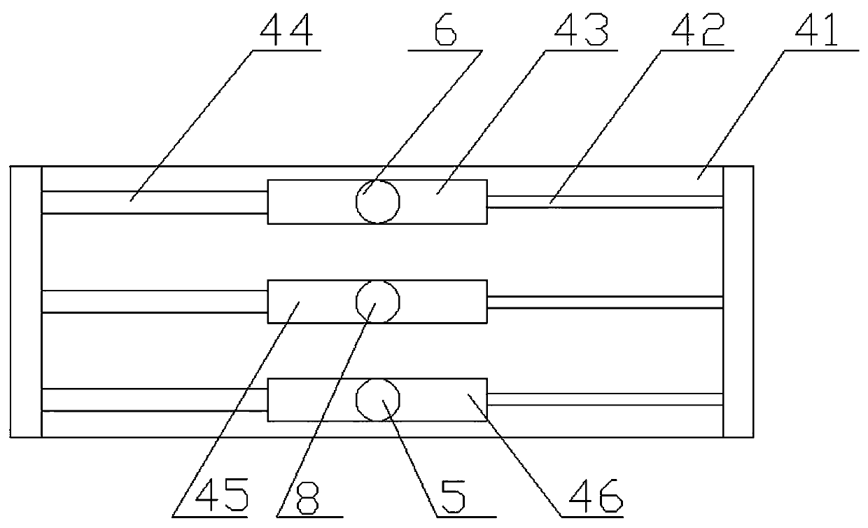
[0051] The support mechanism includes a support base 9 arranged on the ground of the shaft 13, a support column 7 arranged on the support base 9, a support beam 41 arranged on the support column 7, and a support beam 41 arranged on the support column 7. A plurality of walking ...

Embodiment 2

[0065] It differs from Embodiment 1 in that: the gas generator includes a compression tank 16 arranged in the collection tank 25, nitrogen gas arranged in the compression tank 16, and a first electromagnetic pump arranged at the outlet of the compression tank 16 valve 17.

Embodiment 3

[0067] It differs from the second embodiment in that: the supporting base 9 is a ring-shaped supporting base.

[0068] A second electromagnetic valve 20 for exhausting is arranged on the collecting air bag.

[0069] The upper end of the dismountable supporting telescopic arm 6 is arranged on the inverted L-shaped bridge arm.


PUM


Abstract

The invention provides a sewage pipeline cleaning device. The device includes a supporting mechanism arranged on the ground where a shaft is located, a desilting mechanism which is arranged on the supporting mechanism and used for cleaning away silt, a propelling mechanism arranged on the supporting mechanism, a collecting mechanism which is arranged on the propelling mechanism and used for collecting silt, a disassembling and assembling mechanism which is arranged on the supporting mechanism and used for being matched with the propelling mechanism, and a control mechanism which is arranged onthe supporting mechanism and used for controlling the supporting mechanism, the desilting mechanism, the propelling mechanism, the collecting mechanism and the disassembling and assembling mechanismto cooperate with one another. According to the sewage pipeline cleaning device, not only can consumption of a great amount of water be avoided, but also efficient cleaning can be carried out on underground narrow pipelines; the effect of completing thorough desilting at a time is achieved, and efficient cleaning can be conducted after use to prevent the situation that there is a stink caused by the silt after storage since the surface of the device body is attached with the silt.

Description

technical field [0001] The invention relates to the technical field of municipal dredging devices, in particular to a sewage pipeline cleaning device. Background technique [0002] Urban underground drainage pipes are an important system to prevent urban waterlogging and drainage. For many branch drainage systems, the diameter of air pipes is only 600mm and 800mm. Such a small pipeline dredging cannot be operated manually. The existing sedimentation sludge recovery device in the drainage pipeline is that the staff hold the suction hose nozzle connected to the recovery tank equipped with an air suction pump on the ground and enter the drainage pipeline to remove the sediment. The sludge is recovered from the suction hose nozzle to the recovery tank on the ground; because the working environment in the drainage pipe is poor and emits a strong smell, it is difficult to work for a long time and the work efficiency is low. In the knotted state, it is still difficult to suck and ...

Claims


Application Information

Patent Timeline
Patent Type & Authority Applications(China)
IPC IPC(8): E03F9/00
CPCE03F9/005E03F9/007
Inventor 张桂华
Owner 张桂华
Why Eureka
Try Eureka