Sliding shock isolation device with ring beam masonry structure and construction method of sliding shock isolation device

A masonry structure, masonry technology, applied in earthquake resistance, building components, building structure and other directions, can solve problems such as poor earthquake resistance, and achieve the effects of low cost, simple construction and good economy

Pending Publication Date: 2018-05-15
XI'AN UNIVERSITY OF ARCHITECTURE AND TECHNOLOGY
View PDF0 Cites 1 Cited by
  • Summary
  • Abstract
  • Description
  • Claims
  • Application Information

AI Technical Summary

Problems solved by technology

[0004] The purpose of the present invention is to overcome the problem of poor seismic capacity existing in existing masonry structures

Method used


Image

  • Sliding shock isolation device with ring beam masonry structure and construction method of sliding shock isolation device
  • Sliding shock isolation device with ring beam masonry structure and construction method of sliding shock isolation device
  • Sliding shock isolation device with ring beam masonry structure and construction method of sliding shock isolation device

Examples


Embodiment 1

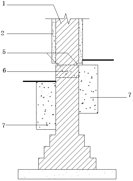
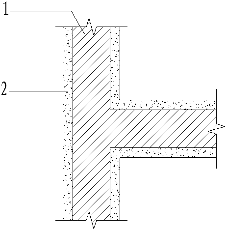
[0041] Such as figure 1 and figure 2 , image 3 , Figure 4 As shown, this embodiment provides a kind of slip isolation device for a masonry structure with ring beam reinforced by high ductility concrete, including the original masonry structure 1, the original masonry structure 1 is provided with a geosphere beam 6, and the geosphere The beam 6 is provided with a weak layer 5, the wall of the original masonry structure 1 above the weak layer 5 is double-sidedly pressed and plastered with a high ductility concrete surface layer 2, and the wall of the original masonry structure 1 below the weak layer 5 is reinforced by pouring on both sides Concrete7. The weak layer 5 is to caulk the 6 mortar joints of the geosphere beam of the original masonry structure 1, and the caulking depth is ≥ 10mm. The original masonry structure 1 is a brick masonry structure with ring beams or a block masonry structure. The thickness of the high ductility concrete surface layer 2 plastered on th...

Embodiment 2

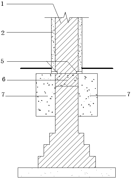
[0048] This embodiment provides a kind of slip isolation device for steel mesh reinforced masonry structure with ring beams, such as Figure 5 and Figure 6 As shown, it includes the original masonry structure 1 and the steel mesh bound on the surface of the original masonry structure 1. The original masonry structure 1 is provided with a geosphere beam 6 below positive and negative zero, and a weak layer 5 is arranged at the geosphere beam 6. The walls of the original masonry structure 1 above the weak layer 5 are plastered with surface layer 2 on both sides, and the walls of the original masonry structure 1 below the weak layer 5 are poured with reinforced concrete 7 on both sides. The weak layer 5 is to caulk the 6 mortar joints of the geosphere beam of the original masonry structure 1, and the caulking depth is ≥ 10mm. Such as Figure 7 , Figure 8 and Figure 9As shown, the steel mesh is composed of vertical steel bars 3, horizontal steel bars 8 and wall-penetrating t...


PUM

PropertyMeasurementUnit
Thicknessaaaaaaaaaa
Thicknessaaaaaaaaaa
Thicknessaaaaaaaaaa

Abstract

The invention provides a sliding shock isolation device with a ring beam masonry structure and a construction method of the sliding shock isolation device, and aims to solve the problem that an existing house with a masonry structure is poor in integrality and poor in shock resistance. The sliding shock isolation structure consists of a masonry original structure, vertical reinforcements, transverse reinforcements, penetration oppositely pulled reinforcements, a high-ductility concrete or cement mortar surface layer, a weak layer, a ground ring beam and reinforcing concrete. By the thinking ofsliding shock isolation, the masonry house is reinforced by the bar-mat reinforcement high-ductility concrete surface layer, a wall can be wrapped by bar-mat reinforcements and high-ductility concrete with high strength and toughness, the integrality of the house is improved, the whole house slips due to slipping breakage of the weak layer, therefore, upward transmitting of seismic force is stopped, meanwhile, the integrality and durability of the masonry house are good, and the sliding shock isolation device is simple to construct and low in engineering cost.

Description

technical field [0001] The invention belongs to the technical field of building structure isolation and reinforcement technology, and in particular relates to a sliding isolation device and a construction method for a masonry structure with ring beams, in particular to a single-layer or multi-layer brick masonry with ring beam or Seismic isolation reinforcement device for block masonry structures. Background technique [0002] The masonry structure is mainly made of blocks and mortar. Due to the large difference in construction quality, relatively low strength, and large discreteness, its tensile, shear, and flexural bearing capacities are low, and its integrity is poor. After the masonry wall cracks in the earthquake, its bearing capacity drops rapidly, and it is easy to collapse, causing huge casualties and serious economic losses in the earthquake area. [0003] The traditional reinforcement method is based on improving the seismic bearing capacity, but because the tradi...

Claims


Application Information

Patent Timeline
IPC IPC(8): E04B1/98E04H9/02E04G21/00
CPCE04G21/00E04H9/02Y02A30/30
Inventor 邓明科李彤叶旺马福栋
Owner XI'AN UNIVERSITY OF ARCHITECTURE AND TECHNOLOGY
Why Eureka
Try Eureka