Embedded-column formwork device and method for constructing fabricated building embedded column by same

A prefabricated, concealed column technology, applied in the connection of formwork/formwork/work frame, formwork/formwork/work frame, on-site preparation of building components, etc. The board is prone to problems such as mold explosion, so as to reduce the construction cost, avoid the mold explosion phenomenon, and improve the quality of the project.

Pending Publication Date: 2018-05-15
NO 2 CONSTR GRP CO LTD OF SHANGHAI CONSTR GRP
View PDF17 Cites 3 Cited by
  • Summary
  • Abstract
  • Description
  • Claims
  • Application Information

AI Technical Summary

Problems solved by technology

[0004] In view of the existing construction process of using prefabricated wallboards instead of templates to pour concealed columns, the prefabricated wallboards are prone to mold explosion and the difficulty of repairing construction is increased

Method used


Image

  • Embedded-column formwork device and method for constructing fabricated building embedded column by same
  • Embedded-column formwork device and method for constructing fabricated building embedded column by same
  • Embedded-column formwork device and method for constructing fabricated building embedded column by same

Examples


Embodiment 1

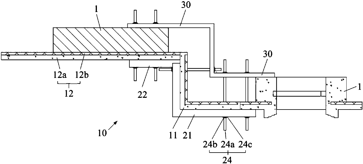
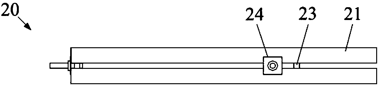
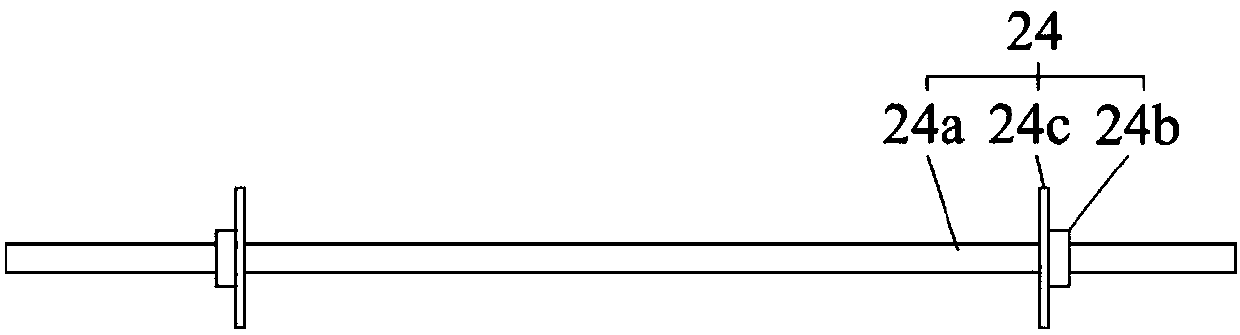
[0031] Example 1: Combining Figure 1 to Figure 4 Illustrate the concealed column formwork device 10 of the present invention, the concealed column 40 of the present embodiment is located at the corners of two adjacent and spaced prefabricated exterior walls 1, and an exterior wall formwork 30 is erected on the outside of the two prefabricated exterior walls 1, and Supported by diagonal braces (not shown in the figure) on the floor surface, the above-mentioned concealed column formwork device 10 includes an L-shaped concealed column panel 11, an I-shaped concealed column panel 12, and a plurality of explosion-proof module assemblies 20, explosion-proof modules Part 20 includes L-shaped reinforcing bar 21, I-shaped reinforcing bar 22 and several connecting pieces 24; figure 1 As shown, the docked L-shaped concealed column panel 11 and I-shaped concealed column panel 12, two adjacent prefabricated exterior walls 1 and exterior wall formwork 30 enclose the area to be poured into ...

Embodiment 2

[0040] Embodiment 2: Different from Embodiment 1, the L-shaped reinforcing rod 21 or I-shaped reinforcing rod 22 of this embodiment is made of a rod with a rectangular cross section, and the L-shaped reinforcing rod 21 or I-shaped reinforcing rod 22 is provided with some bolt holes matched with the pull screw rod 24a of the connector 24, the bolt holes are processed on the reinforcing bar in advance, and the spot is connected with the concealed column panel bolts, which is easy to operate and can realize the technical scheme of the present invention.

Embodiment 3

[0041] Embodiment three: different from embodiment one and embodiment two, such as Figure 5 As shown, the concealed column 40 of this embodiment is located between two prefabricated exterior walls 1 arranged at intervals, rather than at a corner, two I-shaped concealed column panels 12 that are connected, two adjacent prefabricated exterior walls 1, and the exterior Wall formwork 30 surrounds the area to be poured into the concealed column 40, and a plurality of explosion-proof mold assemblies 20 are arranged at intervals along the height direction of the I-shaped concealed column panel 12, such as Figure 6 As shown, after the concrete is cast-in-place and reaches the strength required by the design, the explosion-proof mold assembly 20 is removed to complete the construction of the concealed columns 40 between the prefabricated exterior walls 1 .


PUM


Abstract

The invention discloses an embedded-column formwork device and a method for constructing a fabricated building embedded column by the same, and relates to the technical field of prefabrication engineering, aiming to solve the problems of proneness to formwork explosion and increased correction difficulty in surface plates of existing embedded columns. The embedded-column formwork device comprisesat least one embedded-column surface plate, at least one exterior-wall formwork and a plurality of formwork-explosion resisting components. The embedded-column surface plates are located on one side of two fabricated exterior walls which are arranged at an interval. The exterior-wall formworks are located on the other side of the fabricated exterior walls. The formwork-explosion resisting components are arranged along the height direction of the embedded-column surface plates at intervals. Each formwork-explosion resisting component comprises a reinforcing rod and a plurality of connectors. The reinforcing rods are arranged on the outer side of the embedded-column surface plates. One ends of the connectors penetrate the embedded-column surface plates and the reinforcing rods to be locked and fastened, and the other ends of the connectors penetrate the exterior-wall formworks to be locked and fastened. A to-be-poured region of the embedded column is formed by the embedded-column surfaceplates, the adjacent two fabricated exterior walls and the exterior-wall formworks in an encircling mode. Steel bars are tied in the to-be-poured region of the embedded column, and concrete is pouredon site. After the strength of the concrete meets design requirements, the formwork-explosion resisting components are demounted.

Description

technical field [0001] The invention relates to the technical field of prefabricated assembly engineering, in particular to a concealed column formwork device and a method for constructing an assembled building concealed column using the formwork device. Background technique [0002] During the construction of prefabricated exterior walls of prefabricated buildings, concealed columns need to be constructed at the corresponding positions of adjacent prefabricated exterior wall joints. Usually, prefabricated wall panels are used instead of templates, and prefabricated wall panels are fixed to prefabricated exterior walls by pull bolts. Then, in the area enclosed by the prefabricated wall panels, steel bars were tied and concrete was poured in place. [0003] However, the following problems still exist in the cast-in-place construction of concealed column concrete: the prefabricated wall panels will be subjected to horizontal pressure, especially the lower half of the prefabric...

Claims


Application Information

Patent Timeline
Patent Type & Authority Applications(China)
IPC IPC(8): E04G13/02E04G17/065
CPCE04G13/02E04G17/0652
Inventor 马跃强陈豪石震东陆冬兴成炜宣诚凯
Owner NO 2 CONSTR GRP CO LTD OF SHANGHAI CONSTR GRP
Why Eureka
Try Eureka