Device and method for generating turbulent flow by fluids in plastic pipe and adjusting pipe outside flow

A flow adjustment device and flow adjustment technology, applied in the direction of fluid flow, pipe/pipe joint/pipe fitting, pipe element, etc., can solve the problems of unsatisfactory fluid uniformity, unfavorable compact equipment structure, accelerated pump wear and aging, etc. , to achieve the effect of improving fluid purity and equipment processing quality, saving space and increasing life.

Pending Publication Date: 2018-05-15
新阳硅密(上海)半导体技术有限公司
View PDF7 Cites 6 Cited by
  • Summary
  • Abstract
  • Description
  • Claims
  • Application Information

AI Technical Summary

Problems solved by technology

[0003] At present, many devices that use fluid as the working substance need to mix the fluid evenly, such as mixing the chemical liquid evenly to make the concentration of the fluid consistent everywhere, which requires a pump to drive the rapid circulation in the pipeline, and the power of the pump is large. The fluid circulation speed can be fast, the circulation speed is slow, the fluid uniformity can not meet the requirements, the circulation speed is fast, the pump speed is fast, the energy consumption is high, the wear and aging of the pump is accelerated, the service life is shortened, and the pump needs to be replaced after several years; many fluids The circulation pipeline needs to adjust the flow rate, and the flow rate has a design margin. Starting from the maximum flow rate, reduce the flow rate to just meet the use requirements, save fluid, and reduce the power

Method used


Image

  • Device and method for generating turbulent flow by fluids in plastic pipe and adjusting pipe outside flow
  • Device and method for generating turbulent flow by fluids in plastic pipe and adjusting pipe outside flow
  • Device and method for generating turbulent flow by fluids in plastic pipe and adjusting pipe outside flow

Examples


Embodiment 1

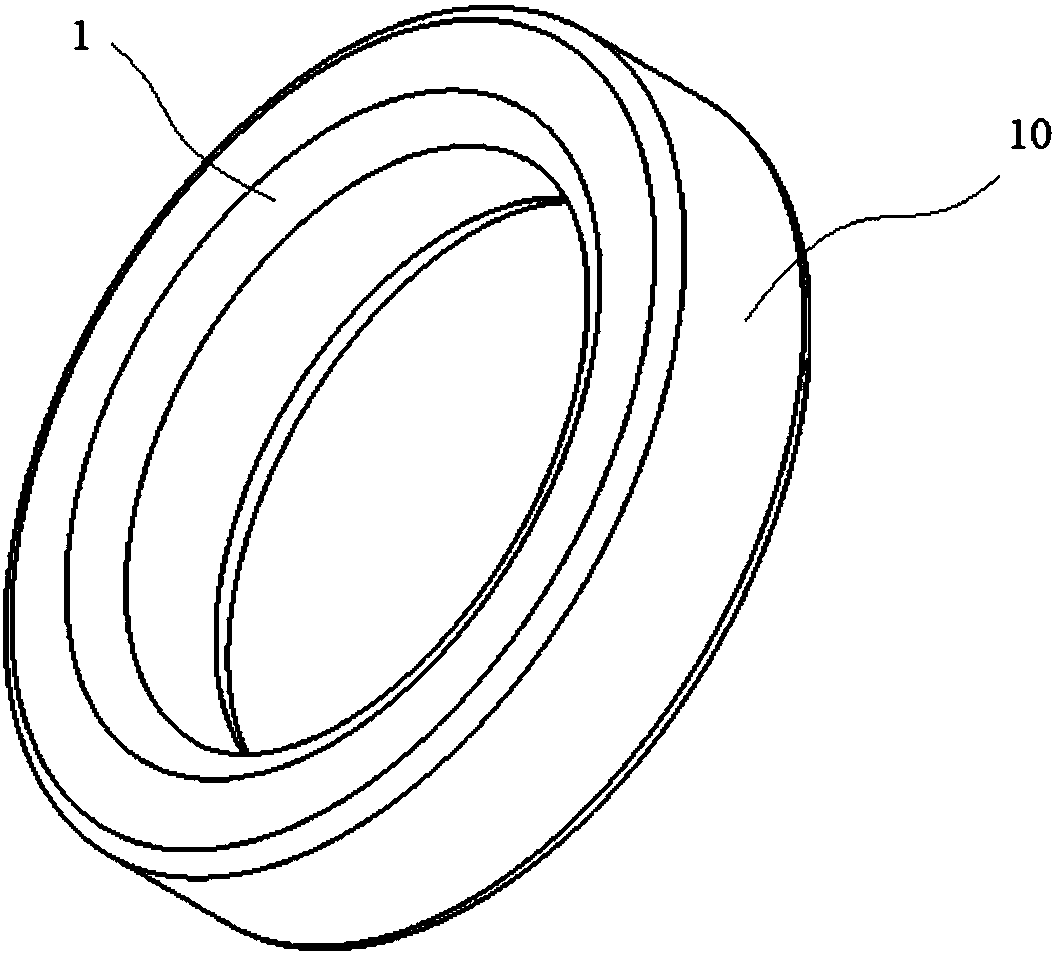
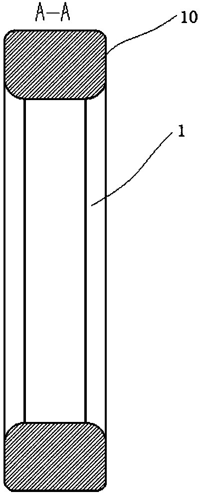
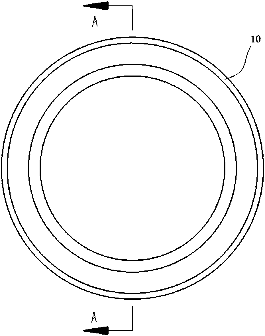
[0047] Embodiment 1: Fluid generates turbulent flow in the plastic pipe and the device and method for regulating the flow outside the pipe, including the extruding device and the plastic pipe 2 . Such as figure 1 , Figure 1a , Figure 1b and Figure 1c As shown, the extrusion device is a sleeve-shaped O-shaped turbulence generation and flow regulating ring 10 made of metal, a circular or oval closed-loop ring, and the two ends of the inner wall are made of smooth arc-shaped chamfers 1, It can be a round chamfer or other smooth arc-shaped chamfers. If the use environment is corrosive, it should be made of anti-corrosion metals such as stainless steel, or coated with anti-corrosion materials on its surface; Figure 4 As shown, put the sleeve-shaped O-shaped turbulent flow generator and flow adjustment ring 10 on the plastic tube 2, squeeze the sleeve-shaped O-shaped turbulent flow generator and flow adjustment ring 10 with pliers or other suitable tools, so that If plastic ...

Embodiment 2

[0048] Embodiment 2: The fluid generates turbulent flow in the plastic tube and the device and method for regulating the flow outside the tube, which includes the extruding device and the plastic tube 2 . Such as Figure 3b As shown, the extrusion device is a bracelet-shaped C-shaped turbulence generation and flow regulating ring 200 made of metal, which is in the above-mentioned image 3 and Figure 3a The O-shaped turbulent flow shown in the bracelet shape has a gap on the basis of the flow adjustment ring 20, such as Figure 3b As shown, the end face of the notch 201 is made with a smooth arc-shaped chamfer 1, which can be a round chamfer or other smooth arc-shaped chamfers; Figure 4 As shown, put the bracelet-shaped C-shaped turbulence generating and flow regulating ring 200 on the plastic tube 2, and squeeze the bracelet-shaped C-shaped turbulent generating and flow regulating ring 200 with pliers or other suitable tools to make it happen. Plastic deformation, after t...

Embodiment 3

[0049] Embodiment 3: The fluid generates turbulent flow in the plastic tube and the device and method for regulating the flow outside the tube, which includes the extruding device and the plastic tube 2 . The extruding device comprises two similar elongated splints 30 with arc-shaped grooves, one side of which is made with arc-shaped grooves 5, and the only difference between the two is that a Figure 5 Both ends of the shown hole 3 are drilled, and the other is shown as Figure 6 Screw holes 4 are drilled at both ends as shown; Figure 9 and Figure 9a As shown, use two screws 31 to connect the two facing elongated splints 30 with arc-shaped grooves, clamp the plastic tube 2 in between, tighten the screws 31, and drive the elongated splints with arc-shaped grooves 30 deform the plastic tube 2 clips; Figure 5 and Figure 6 The corrugation of the elongated splint 30 with an arc-shaped groove in contact with the plastic tube 2 is made into a smooth arc-shaped chamfer 1, and...


PUM


Abstract

The invention relates to a device and a method for generating turbulent flow by fluids in a plastic pipe and adjusting pipe outside flow. When the fluids flow in a pipeline and a cross-sectional shapeand/or an area is changed, the fluids can generate the turbulent flow. By the aid of the phenomenon, a cross-sectional shape and/or area adjusting device is arranged outside the pipeline, so that theturbulent flow is generated, fluid particles are mutually and uniformly blended, a fluid pipeline often needs to turn flow down, a flow adjusting valve is serially connected into the pipeline in prior art, a lot of fine particulate matters can be generated by friction and are mixed into the fluid when the valve acts to adjust the flow in a fluid pipeline of a semiconductor machining device, so that machining quality is affected, the valve is made of good and expensive materials to decrease generation of the particulate matters, and cost is increased. According to the device, an extrusion device sleeves a plastic pipeline, the plastic pipeline is deformed in an extruding manner, the cross-sectional area is decreased, the turbulent flow can be homogenized, the flow can be adjusted, the particulate matters cannot be generated and mixed into the fluids outside the pipeline, the device is simple and reliable, cost is reduced, and device machining quality is improved.

Description

technical field [0001] The invention relates to a fluid pipeline, especially a pipeline using a plastic pipe as a fluid pipeline, which is used in many industrial processing equipment, such as semiconductor wet process equipment. Background technique [0002] Many fluid equipment, such as semiconductor wet process equipment, wafer coating, cleaning, etching, deglue and other equipment, need to use gas or liquid as the working substance. There are many plastic pipes of different thicknesses in the equipment, and the fluid passes through the equipment. Plastic pipes for circulation. [0003] At present, many devices that use fluid as the working substance need to mix the fluid evenly, such as mixing the chemical liquid evenly to make the concentration of the fluid consistent everywhere, which requires a pump to drive the rapid circulation in the pipeline, and the power of the pump is large. The fluid circulation speed can be fast, the circulation speed is slow, the fluid unif...

Claims


Application Information

Patent Timeline
IPC IPC(8): F16L55/00F15D1/10
CPCF15D1/10F16L55/00
Inventor 刘现营
Owner 新阳硅密(上海)半导体技术有限公司
Why Eureka
Try Eureka