A device and method for rapid sampling of soil layers

A technology of soil stratification and sampling device, applied in the direction of sampling device, can solve the problems of reducing sampling efficiency, wasting labor, wasting time, etc., and achieving the effect of increasing the scope of sampling, increasing the scope, and improving work efficiency

Active Publication Date: 2020-02-07
浙江化工工程地质勘察院有限公司
View PDF11 Cites 0 Cited by
  • Summary
  • Abstract
  • Description
  • Claims
  • Application Information

AI Technical Summary

Problems solved by technology

[0004] In the existing sampling method, it is necessary to manually dig out the ring knife and the fixed plate with a shovel at the end, which wastes time and labor and reduces the working efficiency of sampling

Method used


Image

  • A device and method for rapid sampling of soil layers
  • A device and method for rapid sampling of soil layers
  • A device and method for rapid sampling of soil layers

Examples


Embodiment 1

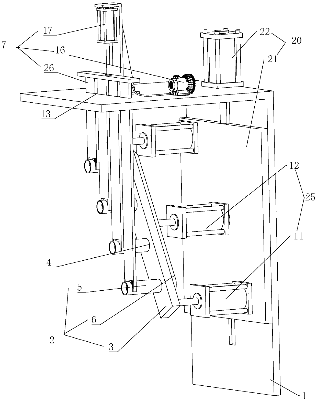
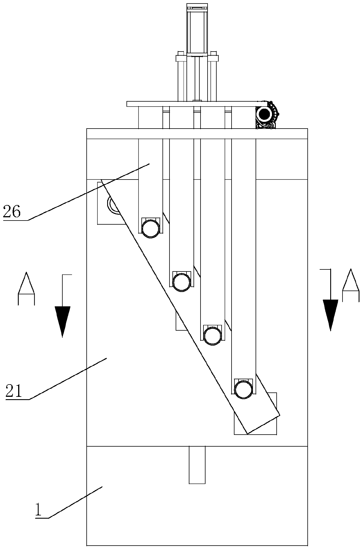
[0037] Embodiment one: a kind of quick sampling device for stratification of soil, such as figure 1 As shown, it includes a bracket 1 on which a sampling assembly 2 for sampling and a driving mechanism 25 fixedly connected to the bracket 1 for driving the sampling assembly 2 are installed.

[0038] like figure 1 As shown, the sampling assembly 2 includes a mounting plate 3 that is slidably connected to the support 1, and a number of mounting holes 4 are equally spaced along the length direction of the mounting plate 3, and a sampling ring 5 is slidably connected to the mounting holes 4. A baffle 6 is fixedly connected to the end of the ring 5 near the support 1; the mounting plate 3 and the baffle 6 are inclined to the horizontal plane, so that each sampling ring 5 does not interfere with each other in the vertical direction, and each sampling ring 5 The height difference between them is 10 centimeters, and the center of the top sampling ring 5 is 10 centimeters away from the...

Embodiment 2

[0051] Embodiment two: the specific steps of a kind of method for layered quick sampling of soil are as follows:

[0052] Step 1: Fix the sampling ring 5 on the baffle 6, and place the sampling ring 5 in the mounting hole 4;

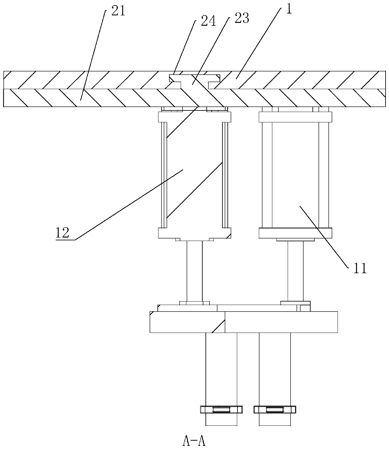
[0053] Step 2: start the drive cylinder, and adjust the height of the bottom plate 21 according to the needs of the test;

[0054] Step 3: Start the first driving cylinder 11, press the mounting plate 3 against the soil surface, start the second driving cylinder 12 to fully insert the sampling ring 5 into the soil;

[0055] Step 4: Start the air pump 16, attach the stopper 8 to the slot 14 at the lower end of the drive plate 26, start the third drive cylinder 17, and insert the drive plate 26 from above to insert the stopper 8 into the soil until the stopper 8 moves To the arc-shaped port 9 of the corresponding sampling loop 5, turn off the air pump 16, start the third drive cylinder 17 to take out the drive plate 26;

[0056] Step 5: Start the first d...


PUM


Abstract

The invention discloses a rapid soil layering sampling device which comprises a bracket, wherein a sampling mechanism for sampling and a driving mechanism for driving the sampling mechanism to insertinto soil are fixedly connected with the bracket; the sampling mechanism comprises a mounting plate mounted on the bracket; a plurality of mounting holes are formed in the mounting plate; sampling rings are connected inside the mounting holes in a sliding manner; baffle plates are fixedly connected with the sampling rings; the sampling rings are not interfered by one another in a vertical direction; a plurality of driving parts are mounted on the bracket; baffle blocks are embedded into the lower parts of the driving parts; embedding grooves are formed in the sampling rings; concave grooves are formed in inner walls of the sampling rings. The sampling rings are completely inserted into soil through the driving mechanism, the baffle blocks are inserted into the soil and embedded into the embedding grooves of the sampling rings through the driving parts, the driving mechanism is then powered on to taken out the sampling rings, outer walls of the sampling rings are cleaned, the sampling rings are covered by upper covers, then sampling is completed, compared with a conventional method, the sampling method is relatively convenient and short in sampling time, and the sampling efficiencyis improved.

Description

technical field [0001] The invention relates to layered sampling of soil samples, in particular to a soil layered rapid sampling device and method. Background technique [0002] In the process of agriculture, forestry, geological survey, building construction, etc., soil sampling is a very important part. [0003] Some existing sampling methods: first fix the ring knife on the fixed plate, hammer the fixed plate with a rubber hammer to insert the ring knife into the soil, then dig out the fixed plate and the ring knife with a shovel, and then test the outer wall of the ring knife Clean up, and finally cover the upper and lower covers to complete the sampling. [0004] In the existing sampling method, it is necessary to manually dig out the ring cutter and the fixed plate with a shovel at the end, which wastes time and labor, and reduces the working efficiency of sampling. Contents of the invention [0005] Aiming at the deficiencies in the prior art, the first purpose of...

Claims


Application Information

Patent Timeline
Patent Type & Authority Patents(China)
IPC IPC(8): G01N1/08
CPCG01N1/08
Inventor 阚家军范勇华
Owner 浙江化工工程地质勘察院有限公司
Why Eureka
Try Eureka