Waterproof power cabinet

A power cabinet and function technology, applied in the field of electric power, can solve the problems of poor heat dissipation, electric shock, easy dent deformation, etc., and achieve the effect of improving work stability, ensuring normal operation, and reasonable internal structure

Inactive Publication Date: 2018-05-15
林永辉
View PDF0 Cites 4 Cited by
  • Summary
  • Abstract
  • Description
  • Claims
  • Application Information

AI Technical Summary

Problems solved by technology

[0002] The structural strength of the traditional power cabinet top cover is poor, and it is easy to sag and deform, resulting in a reduced safety distance from the live conductors in the cabinet, and there are potential accidents such as electric shock and short circuit; The internal temperature of the cabinet is too high, so that the components cannot work reliably or the service life is reduced, and the internal components of the power cabinet are prone to heat or short circuit
In order to facilitate installation and maintenance, the position of the power cabinet is generally not too high, and the general wind and rain will not have any impact on the power cabinet, but in the case of heavy rain, poor drainage in the city, and waterlogging, the power cabinet It is easy to be submerged in water and affect the normal operation of internal terminal equipment
In addition, the general power cabinet cannot be moved and fixed very conveniently, and the convenience is not high, and the phenomenon of sliding of the power cabinet often occurs during the work process, which affects the normal operation of the internal equipment of the power cabinet; therefore, we need a Waterproof power cabinet

Method used


Image

  • Waterproof power cabinet
  • Waterproof power cabinet
  • Waterproof power cabinet

Examples


Embodiment Construction

[0015] The technical solution of this patent will be further described in detail below in conjunction with specific embodiments.

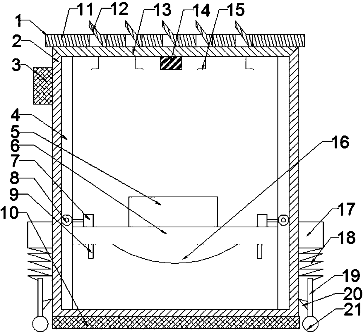
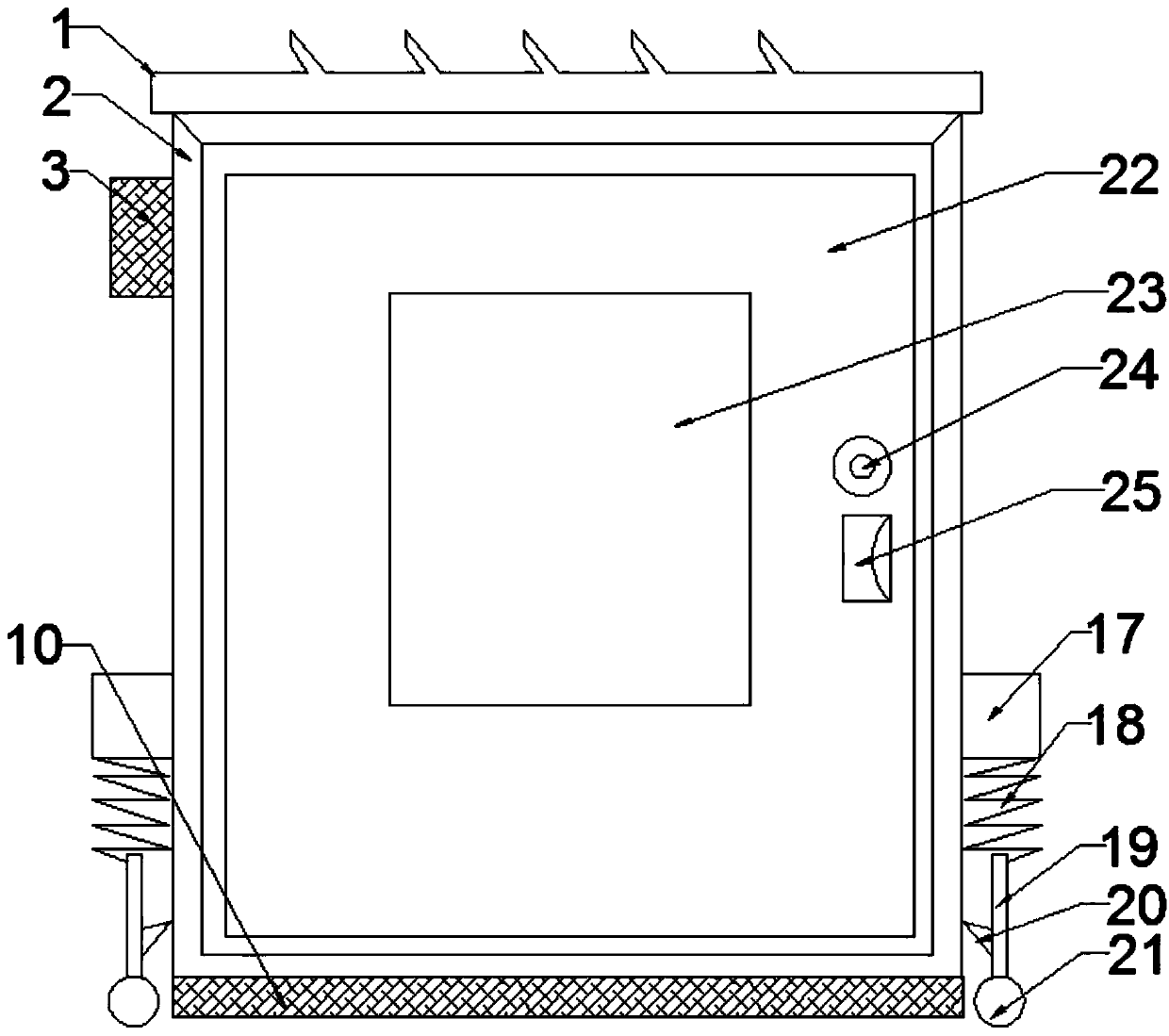
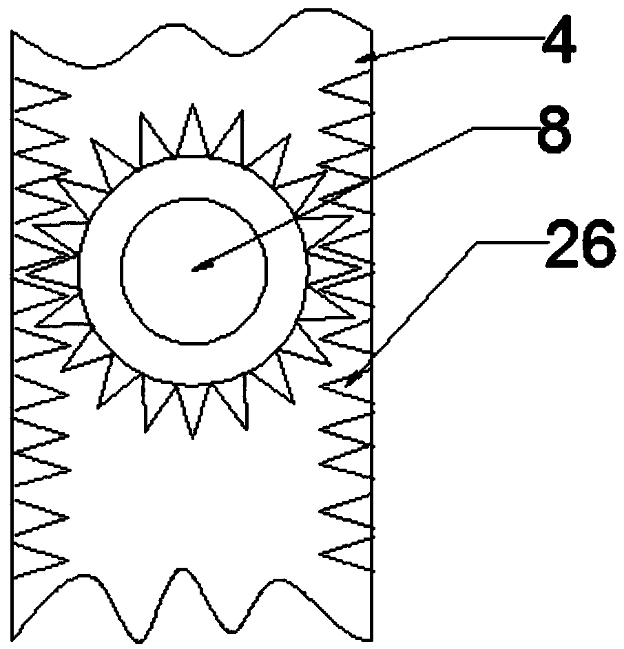
[0016] see Figure 1-3 , a power cabinet with waterproof function, including a power cabinet device and a mobile device; , water level sensor 9, anti-skid plate 10, top cover top plate 11, heat sink 12, top cover bottom plate 13, Hall element 14, cable buckle 15, floating body 16, cabinet door 22, observation window 23, cabinet door lock 24, handle 25 and rack 26; the lower side of the cabinet body 2 is fixedly provided with an anti-skid plate 10, and the upper side of the cabinet body 2 is provided with a top cover 1, and the top cover 1 includes a top cover top plate 11 and a top cover bottom plate 13, and a top cover top plate 11 It is fixedly connected with the top cover bottom plate 13; the top cover top plate 11 is provided with a heat sink 12 formed by one stamping, and the heat sink 12 and the top cover top plate 11 form an inclined settin...


PUM


Abstract

The invention discloses a waterproof power cabinet which comprises an electric cabinet device and a moving device. An antiskid plate is fixedly arranged on the lower side of the cabinet body. A top cover is arranged on the upper side of the cabinet body. The top cover comprises a top cover top plate and a top cover bottom plate. The top cover top plate and the top cover bottom plate are fixedly connected. A gear and a rack are meshed. A water level sensor is arranged at the bottom of a mounting frame. Two pairs of rollers are arranged on the lower outer walls of left and right sides of the cabinet body. The rollers and plate bodies are connected. Mounting plates are arranged on middle side walls of left and right sides of the cabinet body. The lower side of each mounting plate is connectedwith a spring. The bottom end of each spring is connected with a plate body. A hook is arranged on the right side wall of each plate body. According to the invention, the double-layered top cover isused; a certain tilt angle is between each heat sink and the top cover, so that the heat dissipation effect is good; and the waterproof power cabinet can automatically adjust the height of the mounting frame according to the water level to ensure that a terminal device is not damaged, can effectively cope with the overflow of rain, and has the advantages of easy fixing and movement and high applicability.

Description

technical field [0001] The invention relates to the field of electric power, in particular to a power cabinet with a waterproof function. Background technique [0002] The structural strength of the traditional power cabinet top cover is poor, and it is easy to sag and deform, resulting in a reduced safety distance from the live conductors in the cabinet, and there are potential accidents such as electric shock and short circuit; The internal temperature of the cabinet is too high, so that the components cannot work reliably or the service life is reduced, and the internal components of the power cabinet are prone to heat or short circuit. In order to facilitate installation and maintenance, the position of the power cabinet is generally not too high, and the general wind and rain will not have any impact on the power cabinet, but in the case of heavy rain, poor drainage in the city, and waterlogging, the power cabinet It is easy to be submerged in water and affect the norm...

Claims


Application Information

Patent Timeline
Patent Type & Authority Applications(China)
IPC IPC(8): H02B1/30H02B1/28H02B1/32H02B1/56
CPCH02B1/303H02B1/052H02B1/28H02B1/306H02B1/34H02B1/565
Inventor 林永辉
Owner 林永辉
Why Eureka
Try Eureka