
Polishing and grinding device for inner wall of glass pipeline

A technology for polishing and grinding glass tubes, which is applied in the direction of grinding drive devices, machine tools for surface polishing, grinding/polishing equipment, etc. It can solve problems such as inability to guarantee the grinding effect, harsh working environment, and poor grinding linkage, and achieve simple structure , easy operation and less power input

Inactive Publication Date: 2018-05-18
合肥挺泰环保科技有限公司
View PDF3 Cites 8 Cited by
  • Summary
  • Abstract
  • Description
  • Claims
  • Application Information

AI Technical Summary

Problems solved by technology

[0002] The glass pipe is a light, high-strength, corrosion-resistant non-metallic pipe. It is made of glass fibers with a resin matrix that are wound on the rotating mandrel layer by layer according to the process requirements, and evenly spread quartz sand at a distance between the fibers. As a sand layer, it ensures the stability and reliability of the pipeline. The glass tube is in the shape of a cylinder, and there are many burrs on the inner wall of the formed glass tube. These burrs must be polished and polished before they are officially used. Currently Most of the grinding operations are manual operations, and the working environment is harsh. At the same time, grinding and polishing are the links with high labor costs in the processing process. Of course, some manufacturers currently use special grinding equipment for operations, but the grinding linkage is poor. Either the grinding head The reciprocating motion form of the grinding head, or the rotation form of the grinding head, the two are not effectively combined, and there are certain defects in the structure of the grinding head, which cannot guarantee a good grinding effect

Method used


Image

  • Polishing and grinding device for inner wall of glass pipeline
  • Polishing and grinding device for inner wall of glass pipeline

Examples


Embodiment Construction

[0015] The following will clearly and completely describe the technical solutions in the embodiments of the present invention with reference to the accompanying drawings in the embodiments of the present invention. Obviously, the described embodiments are only some, not all, embodiments of the present invention.

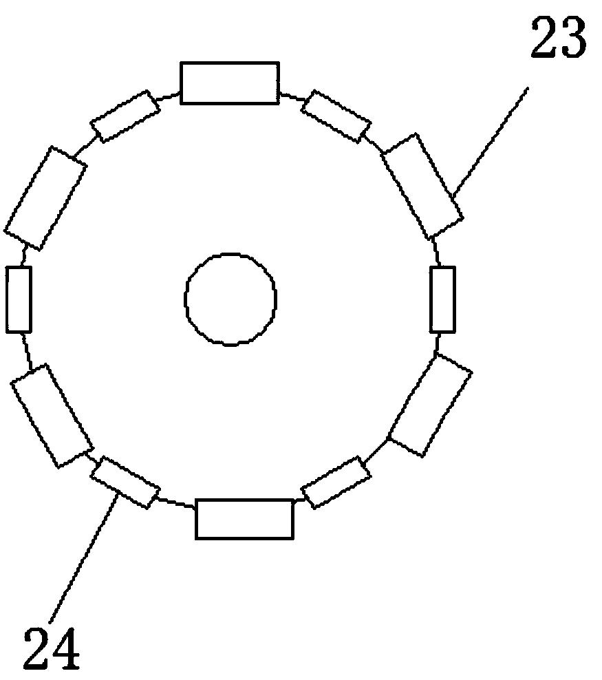
[0016] refer to Figure 1-2 , a glass pipe inner wall polishing device, comprising a base plate 1 and a lead screw 10, the lead screw 10 is arranged on the top of the base plate 1 in parallel, the lower end of the base plate 1 is rectangularly distributed with four mounting feet 22, and the four mounting feet 22 are connected to the base plate 1 Fixedly connected, the cylindrical surface of the lead screw 10 is covered with a sleeve 12, which is the same as limiting the degree of freedom of the lead screw 10, and the inner wall of the sleeve 12 is provided with an internal thread corresponding to the external thread of the lead screw 10, which is used to connect the l...


PUM


Abstract

The invention discloses a polishing and grinding device for the inner wall of a glass pipeline. The device comprises a bottom plate and a lead screw, wherein the lead screw is arranged above the bottom plate in parallel; four mounting legs are rectangularly distributed at the lower end of the bottom plate and are fixedly connected to the bottom plate; a sleeve sleeves the column surface of the lead screw; an inner thread corresponding to an outer thread of the lead screw is arranged on the inner wall of the sleeve; the sleeve is fixedly connected to the bottom plate through a sleeve support; the end, close to the sleeve, of the lead screw is fixedly connected to a joint bearing; the end, far from the lead screw, of the joint bearing is fixedly connected to a connecting block; and a connecting rod is hinged to the connecting block. The device disclosed by the invention is simpler in structure, small in power input and strong in co-movement, and is stronger in co-movement compared with that of an existing device in structure while solving the problem that the manual grinding cost is high. A grinding head also reciprocates in the glass pipeline while rotating. In addition to the action of oilstones and an asbestosed wire gauze, the grinding and polishing effect is better.

Description

technical field [0001] The invention relates to the field of polishing and grinding equipment, in particular to a polishing and grinding device for the inner wall of a glass pipe. Background technique [0002] The glass pipe is a light, high-strength, corrosion-resistant non-metallic pipe. It is made of glass fibers with a resin matrix that are wound on the rotating mandrel layer by layer according to the process requirements, and evenly spread quartz sand at a distance between the fibers. As a sand layer, it ensures the stability and reliability of the pipeline. The glass tube is in the shape of a cylinder, and there are many burrs on the inner wall of the formed glass tube. These burrs must be polished and polished before they are officially used. Currently Most of the grinding operations are manual operations, and the working environment is harsh. At the same time, grinding and polishing are the links with high labor costs in the processing process. Of course, some manufa...

Claims


Application Information

Patent Timeline
Patent Type & Authority Applications(China)
IPC IPC(8): B24B29/08B24B41/06B24B47/20B24B57/02
CPCB24B29/08B24B41/067B24B47/20B24B57/02
Inventor 吴小飞
Owner 合肥挺泰环保科技有限公司
Learn More