Steel pipe polishing device
A steel pipe and grinding wheel technology, which is used in grinding drive devices, grinding/polishing safety devices, grinding machines, etc., can solve the problems of poor surface quality, poor safety, low efficiency, etc., to reduce the impact of air quality, use Safe, convenient and reliable work
- Summary
- Abstract
- Description
- Claims
- Application Information
AI Technical Summary
Problems solved by technology
Method used
Image

Examples
Embodiment
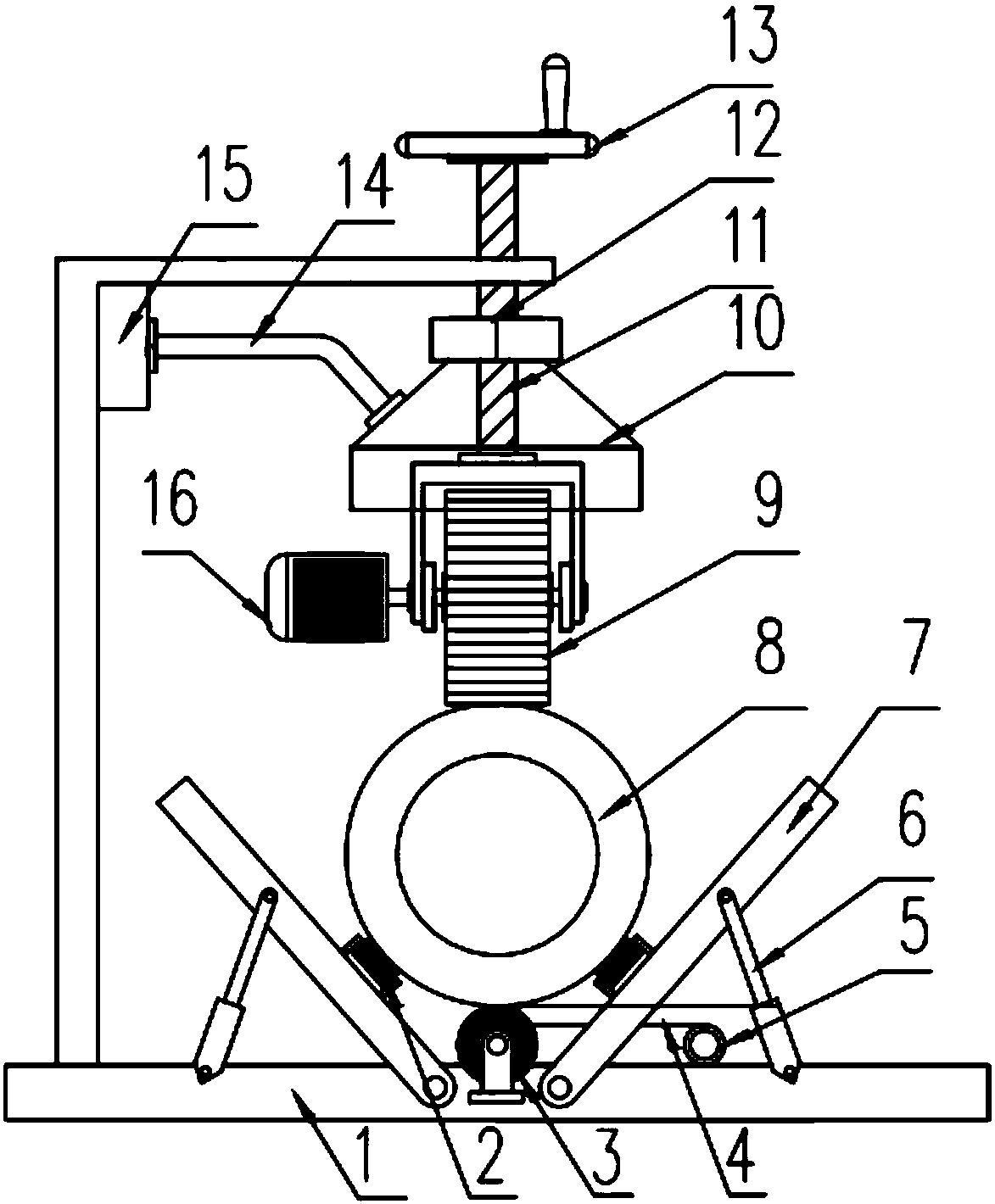
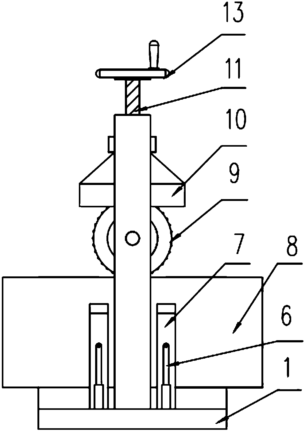
[0023] as attached figure 1 , 2 shown
[0024] The invention provides a steel pipe grinding device, which is characterized in that it includes a base 1, a roller 2, a grinding wheel 3, a transmission belt 4, a grinding motor 5, a hydraulic cylinder 6, a support plate 7, a steel pipe 8, a propulsion roller 9, and a dust collection cover 10 , lead screw 11, nut 12, hand wheel 13, connecting hose 14, dust suction fan 15 and motor 16; the left and right sides of the upper end of the base 1 are respectively symmetrically hinged with two support plates 7, and the two symmetrical supports along the central axis of the base 1 The support plates 7 form a V-shaped support structure, and a roller 2 is respectively installed on the inner surface of each support plate 7, and the four support plates 7 are respectively hinged to the base 1 through a hydraulic cylinder 6, and the V-shaped support structure located at one end of the base 1 The axis of symmetry is provided with a grinding whe...
PUM
 Abstract
Description
Claims
Application Information
 - Generate Ideas
- Intellectual Property
- Life Sciences
- Materials
- Tech Scout
- Unparalleled Data Quality
- Higher Quality Content
- 60% Fewer Hallucinations
Browse by: Latest US Patents, China's latest patents, Technical Efficacy Thesaurus, Application Domain, Technology Topic, Popular Technical Reports.
© 2025 PatSnap. All rights reserved.Legal|Privacy policy|Modern Slavery Act Transparency Statement|Sitemap|About US| Contact US: help@patsnap.com