Throttle valve with cleaning structure and flow-slowing structure and capable of adjusting flow rate

An adjustable and clean technology, applied in the direction of cleaning methods and appliances, chemical instruments and methods, valve housing structure, etc., can solve the problems of no cleaning structure, increase the labor burden of the staff, and unable to clean the valve, so as to extend the service life, Effects of reduced labor burden and simple structure

Inactive Publication Date: 2018-05-18
丁锋燕
View PDF0 Cites 5 Cited by
  • Summary
  • Abstract
  • Description
  • Claims
  • Application Information

AI Technical Summary

Problems solved by technology

[0006] Aiming at the deficiencies of the prior art, the present invention provides a throttling method with a clean and slow flow structure and an adjustable flow rate, which can clean the inside of the valve and prevent the growth of moss and other sundries that damage the water quality inside the valve, without regular cleaning. Clean, greatly reducing the labor burden of the staff, preventing the water flow from being too fast and causing damage to various structures, increasing the service life, adjusting the elasticity of the buffer spring, thereby adjusting the speed of the water flow, easy to operate, easy to use, and preventing artificial or other factors. The situation that the knob is damaged, the service life is extended, the structure is simple, convenient and practical, etc. It solves the problem that most of the existing throttle valves have no cleaning structure, and the inside of the valve cannot be cleaned. Regular cleaning is often required, which increases the staff's workload. labor burden problem

Method used


Image

  • Throttle valve with cleaning structure and flow-slowing structure and capable of adjusting flow rate
  • Throttle valve with cleaning structure and flow-slowing structure and capable of adjusting flow rate
  • Throttle valve with cleaning structure and flow-slowing structure and capable of adjusting flow rate

Examples


Embodiment Construction

[0027] The following will clearly and completely describe the technical solutions in the embodiments of the present invention with reference to the accompanying drawings in the embodiments of the present invention. Obviously, the described embodiments are only some, not all, embodiments of the present invention. Based on the embodiments of the present invention, all other embodiments obtained by persons of ordinary skill in the art without making creative efforts belong to the protection scope of the present invention.

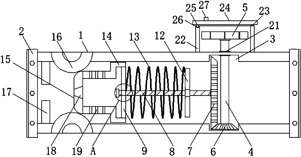
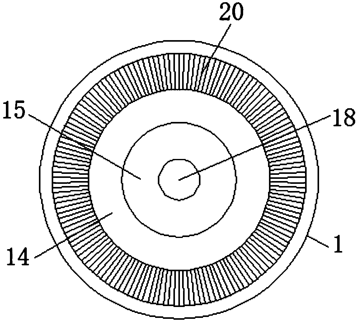
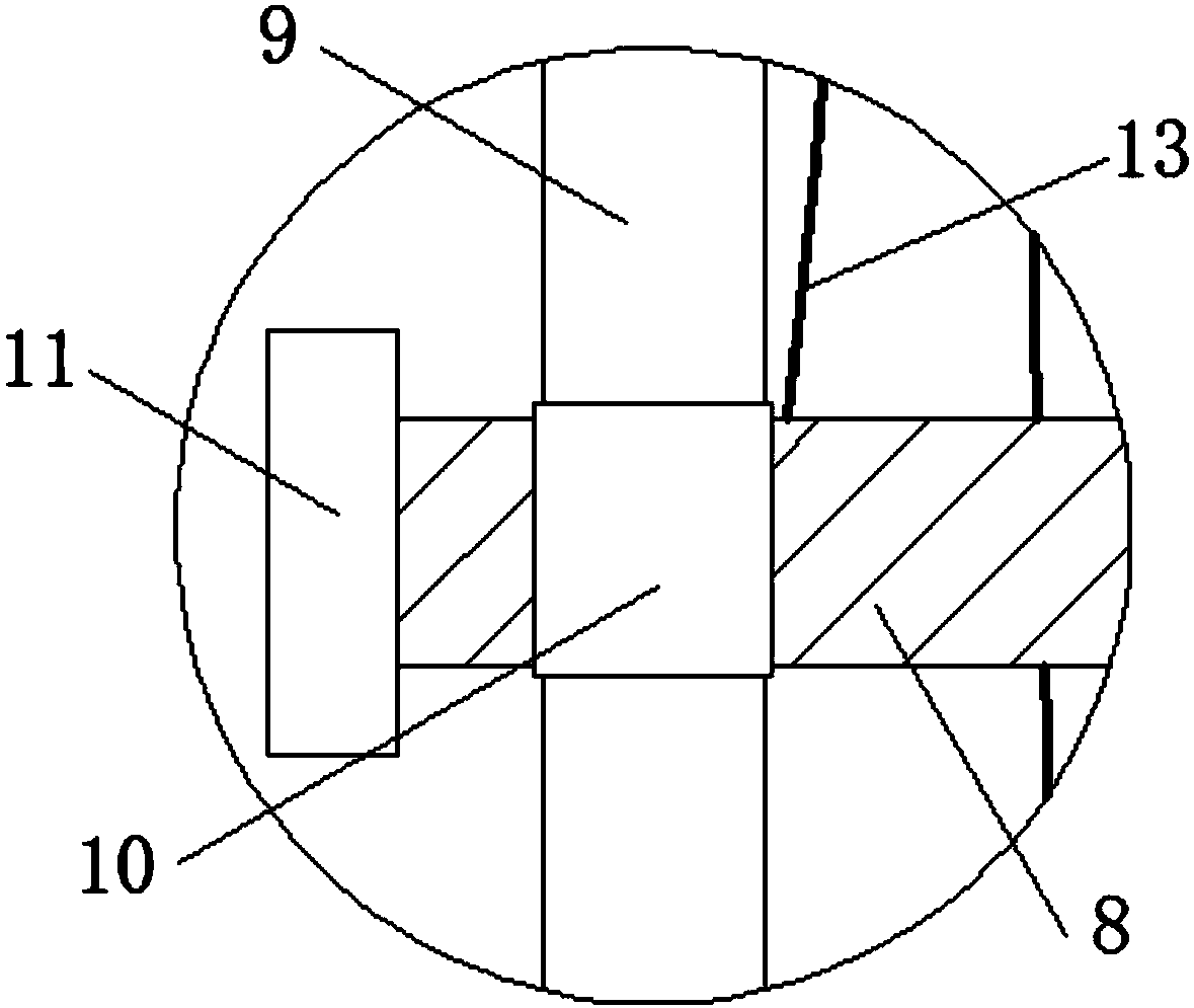
[0028] see Figure 1-3 , a throttling method with a clean and slow flow structure and adjustable flow rate, comprising a valve body (1), flanges (2) are installed at the inlet and outlet of the valve body (1), and the inner wall of the valve body (1) A regulating rod (4) is movably installed through the groove (3) opened on the top, and a seal (21) is fixedly installed at the junction of the regulating rod (4) and the valve body (1), where the groove (3) is lo...


PUM


Abstract

The invention relates to the technical field of one-way valves, and discloses a throttle valve with a cleaning structure and a flow-slowing structure and capable of adjusting the flow rate. Accordingto the throttle valve, a screw rod (8), a supporting plate (9), a threaded joint (10), a clamping plate (14), a brush (20) and the like are arranged, water flow pushes the clamping plate (14) so thatthe supporting plate (9) can move and rotate on the screw rod (8) through the threaded joint (10), and therefore the brush (20) on the clamping plate (14) is driven to clean the interior of a valve body; and meanwhile, a buffer spring (13) is matched to drive the supporting plate (9) to move and rotate back and forth, and therefore the brush (20) can clean the interior of the valve body all the time, sundries such as moss which can destroy water quality can be prevented from growing in the valve body, periodical cleaning is not needed, and the labor burden of workers can be greatly reduced.

Description

technical field [0001] The invention relates to the technical field of one-way valves, in particular to a throttling method with a clean and slow flow structure and adjustable flow velocity. Background technique [0002] Valves are the control components in the fluid delivery system. They have the functions of cut-off, adjustment, flow diversion, reverse flow prevention, pressure stabilization, flow diversion or overflow pressure relief. Valves used in fluid control systems range from the simplest cut-off valve to extremely complex The various valves used in the automatic control system have a wide variety of varieties and specifications. The valves can be used to control the flow of various types of fluids such as air, water, steam, various corrosive media, mud, oil, liquid metal and radioactive media. . [0003] The throttle valve is a valve that controls the fluid flow by changing the throttle section or throttle length. If the throttle valve and the check valve are conn...

Claims


Application Information

Patent Timeline
Patent Type & Authority Applications(China)
IPC IPC(8): F16K1/04F16K47/04F16K47/08F16K31/53F16K27/08B08B9/04
CPCF16K1/04B08B9/04F16K27/08F16K31/53F16K47/04F16K47/08
Inventor 丁锋燕
Owner 丁锋燕
Why Eureka
Try Eureka