Micro harmonic speed reducer

A harmonic reducer, micro technology, applied in mechanical equipment, transmission parts, belts/chains/gears, etc., can solve the problems of unsuitable application, space limitation, large space, etc., to reduce material cost, light weight, Small size effect

Inactive Publication Date: 2018-05-22
苏州习元智能科技有限公司
View PDF16 Cites 3 Cited by
  • Summary
  • Abstract
  • Description
  • Claims
  • Application Information

AI Technical Summary

Problems solved by technology

For small joints such as micro-robots or robot fingers, the space available for the installation of the reducer is greatly limited due to the limitation of the shape and structure.
The defect of the tra

Method used


Image

  • Micro harmonic speed reducer
  • Micro harmonic speed reducer
  • Micro harmonic speed reducer

Examples


Embodiment Construction

[0025] The following will clearly and completely describe the technical solutions in the embodiments of the present invention with reference to the accompanying drawings in the embodiments of the present invention. Obviously, the described embodiments are only some, not all, embodiments of the present invention. Based on the embodiments of the present invention, all other embodiments obtained by persons of ordinary skill in the art without creative efforts fall within the protection scope of the present invention.

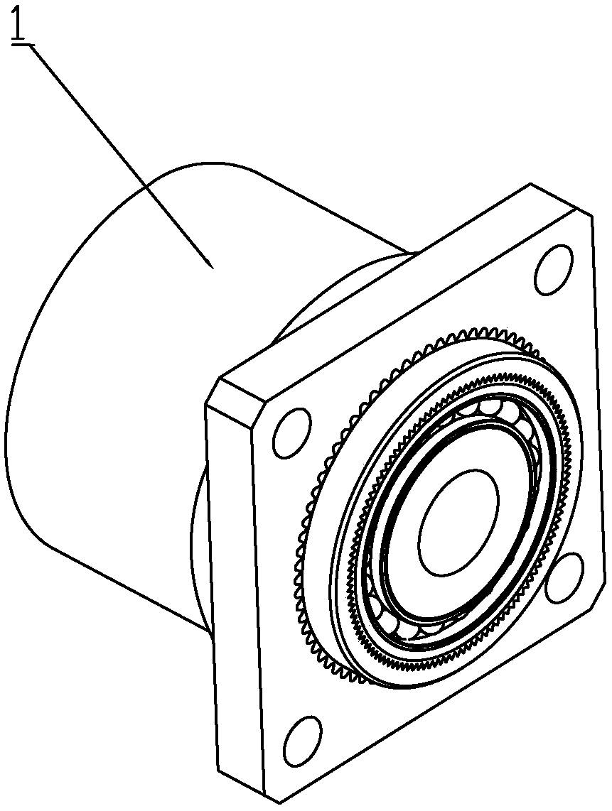
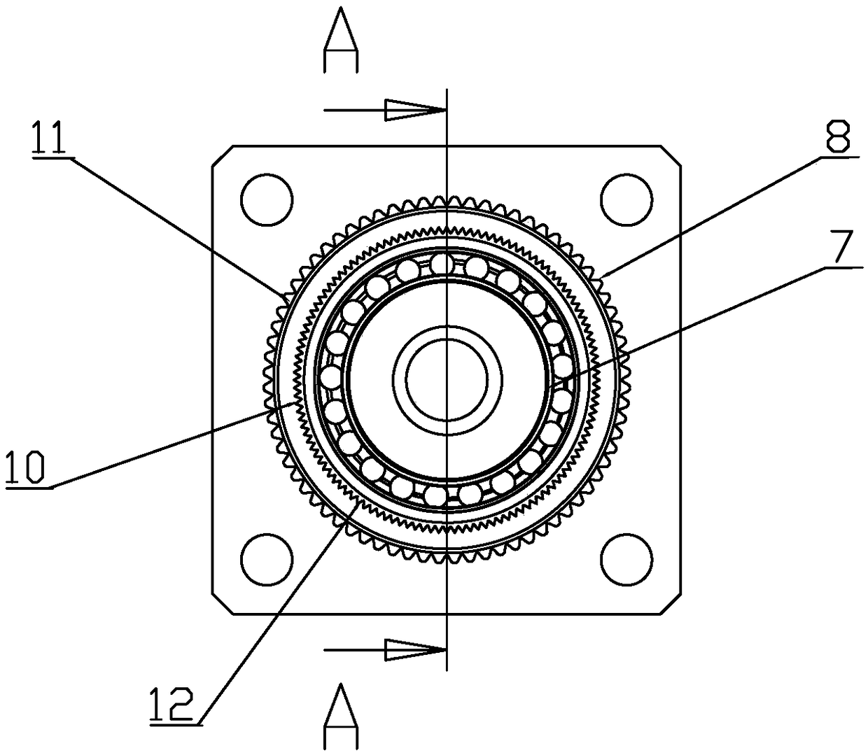
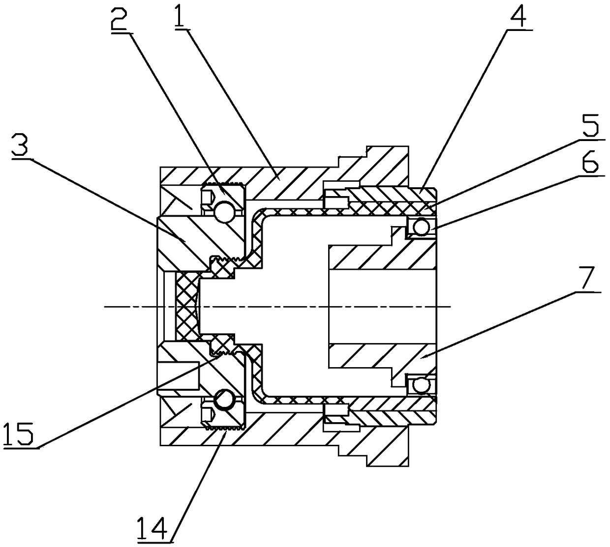
[0026] according to Figure 1 to Figure 8 , the present invention provides a miniature harmonic reducer, including a housing 1, a bearing outer ring 2, a bearing inner ring 3, a rigid wheel 4, a flexible wheel 5, a flexible bearing 6, a wave generator 7, and an inner gear ring of the shell head 8. Shell tail internal thread 9, rigid wheel internal gear ring 10, rigid wheel external gear ring 11, soft head external gear ring 12, soft tail external thread 13, bearing...


PUM


Abstract

The invention discloses a micro harmonic speed reducer. The micro harmonic speed reducer comprises a shell body, an outer bearing ring, an inner bearing ring, a rigid wheel, a flexible wheel, a flexible bearing, a wave generator, an inner shell head tooth ring, an inner shell tail thread, an inner rigid wheel tooth ring, an outer rigid wheel tooth ring, an outer flexible head tooth ring, an outerflexible tail thread, an outer bearing thread and an inner bearing thread, wherein the inner shell head tooth ring of the shell body and the outer rigid wheel tooth ring of the rigid wheel are mutually fixedly connected in an embedding manner; and the inner rigid wheel tooth ring and the outer flexible head tooth ring form tooth joint, the outer flexible head tooth ring is equipped with the wave generator through the flexible bearing, the inner shell tail thread and the outer bearing thread are mutually screwed and fixed, and the outer flexible tail thread and the inner bearing thread are mutually screwed and fixed. According to the micro harmonic speed reducer disclosed by the invention, the total volume and weight are relatively greatly reduced with the adoption of screw joint and the embedded tooth joint; the micro harmonic speed reducer is small in size, light in weight and stable in transmission; the micro harmonic speed reducer is of great significance in projects with quality and volume requirements; and moreover, a process of machining thread holes and a link of assembling screws are omitted, so that the assembly efficiency is greatly increased.

Description

technical field [0001] The invention relates to the field of harmonic reducer technical equipment, in particular to a miniature harmonic reducer. Background technique [0002] Harmonic reducer is a high-precision transmission reduction device, which is mainly composed of three basic components: wave generator, flexible spline and rigid spline. Mesh to transmit motion and power. [0003] In the prior art, the transmission parts of the simulation robot, such as legs, arms, fingers, and torso, all adopt harmonic reducers. For small joints such as micro-robots or robot fingers, the space available for the installation of the reducer is greatly limited due to the limitation of the shape and structure. The defect of the traditional reducer is that most of the shells, inner and outer rings, rigid wheels and flexible wheels are connected by several screws, which will occupy a large space and are not suitable for application. Contents of the invention [0004] In order to solve ...

Claims


Application Information

Patent Timeline
IPC IPC(8): F16H49/00F16H57/023F16H57/035
CPCF16H49/001F16H57/023F16H57/035
Inventor 郁华明李孝锋孙景英
Owner 苏州习元智能科技有限公司
Why Eureka
Try Eureka