Micromirror-based shared window laser radar system
A lidar and micromirror technology, applied in the field of shared window lidar systems, can solve the problems of complex receiving optical path, increase system volume and cost, and difficulty in applying portable equipment, and achieves increasing scanning frequency, reducing equipment volume, and widening The effect of application scenarios
- Summary
- Abstract
- Description
- Claims
- Application Information
AI Technical Summary
Problems solved by technology
Method used
Image
Examples
Embodiment 1
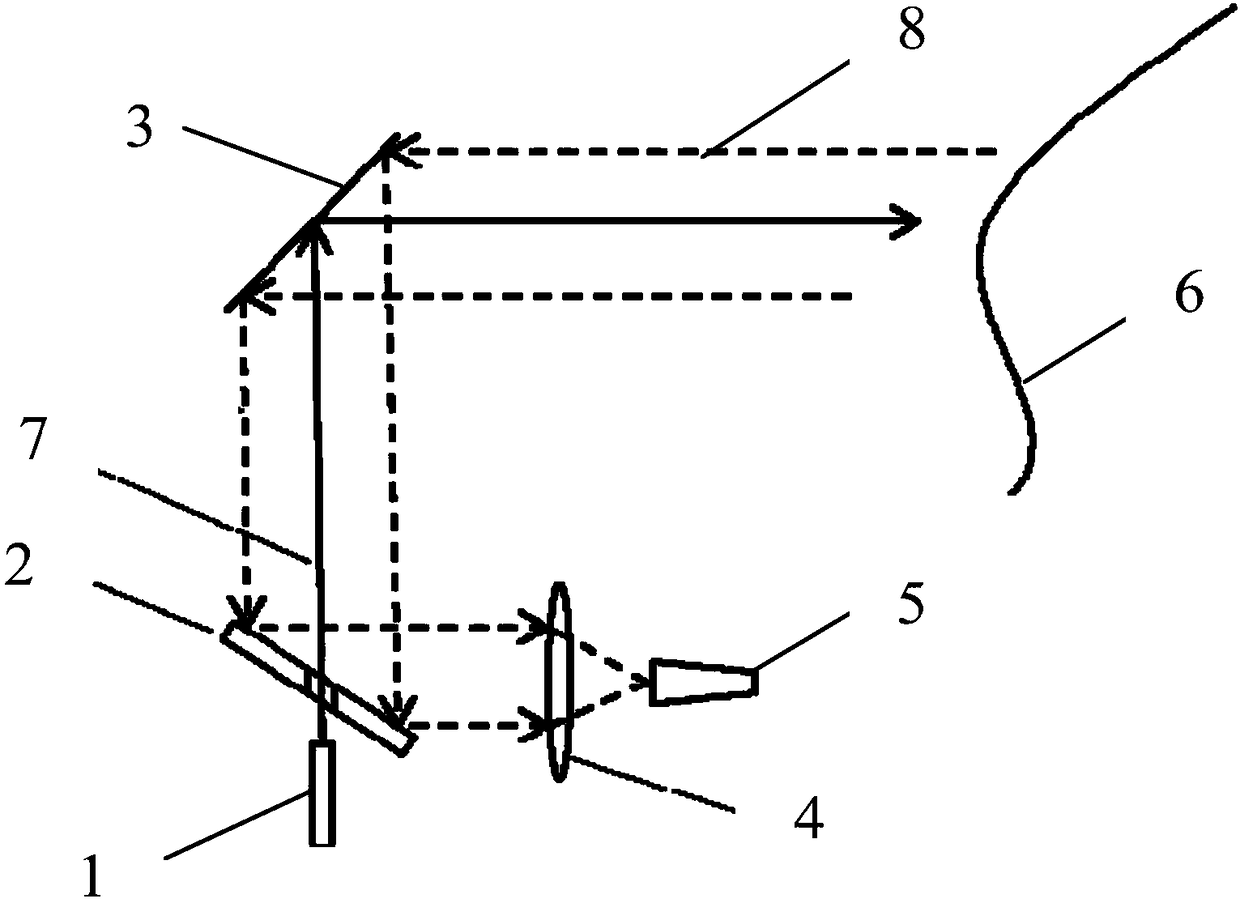
[0027] Such as figure 1 As shown, the present invention provides a shared window lidar system based on micromirrors, comprising: a laser 1, a single mirror 2, a micromirror 3, a converging lens 4 and an optical detector 5;
[0028] A first through hole is opened on the one-way mirror 2;
[0029] The laser beam 7 generated by the laser 1 is emitted to the micromirror 3 through the first through hole, and then emitted to the detection target 6 through the micromirror 3;
[0030] The echo light beam 8 reflected back from the detection target 6 is reflected to the single-sided mirror 2 by the micromirror 3, then reflected to the convergent lens 4 by the single-sided emitter mirror, and then passed through the convergent lens 4 Converge to the photodetector 5.
[0031] Preferably, the laser 1 is a pulsed laser 1 .
[0032] The laser 1 may be a semiconductor edge emitting laser 1 , a vertical surface cavity emitting semiconductor laser 1 , a fiber laser 1 or the like.
[0033] T...
Embodiment 2
[0043] In the lidar system described in Embodiment 1, the micromirror 3 is an important optical relay component and scanning device in the optical path. On the one hand, the size of the reflection surface of the micromirror 3 defines the maximum reflection area; on the other hand, the micromirror 3 realizes the scanning of the light beam based on its own scanning structure.
[0044] Further, the micromirror 3 is a dynamically deformable micromirror.
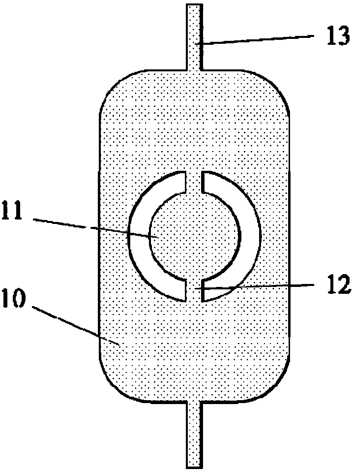
[0045] In the present embodiment two, the basic structure of the mirror surface of the micromirror 3 is as follows: figure 2 As shown, it includes an outer mirror 10 and an inner mirror 11. The inner mirror 11 is connected to the outer mirror 10 via a connecting mechanism 12, and the outer mirror 10 is connected to an external fixed anchor point through a torsion shaft 13. The outer mirror 10, the inner mirror 11 and the connection mechanism 12 form a whole to rotate around the rotation axis, and the connection mechanism 12 is ...
Embodiment 3
[0049] exist figure 2 A structure of the micromirror 3 is shown in , in which the inner mirror 11 is rotated about the axis of rotation. During the rotation and oscillation process, the natural rotational frequency of the micromirror as a whole is determined by the total moment of inertia of the micromirror and the stiffness coefficient of the torsion axis 13 . Therefore, by adjusting the shape and size of the connecting mechanism 12, the overall rotation frequency of the micromirror is much lower than the natural frequency of the vibrator formed by the connecting mechanism 12 and the inner mirror 11. The size of the connecting mechanism 12 can be adjusted by adjusting the first width ( H1 ) and the first distance ( L1 ), and the shape of the connecting mechanism 12 can be formed by changing the etched pattern.
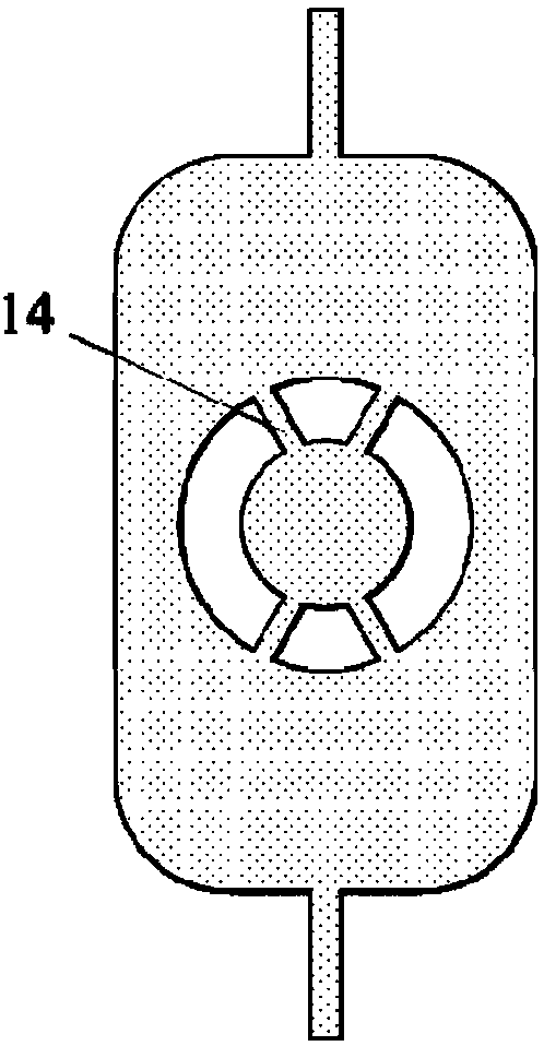
[0050] exist image 3 In the micromirror structure shown, four arc-shaped grooves are etched on the same circumference on the SOI with the center of the inner mirr...
PUM
 Abstract
Description
Claims
Application Information
 - R&D
- Intellectual Property
- Life Sciences
- Materials
- Tech Scout
- Unparalleled Data Quality
- Higher Quality Content
- 60% Fewer Hallucinations
Browse by: Latest US Patents, China's latest patents, Technical Efficacy Thesaurus, Application Domain, Technology Topic, Popular Technical Reports.
© 2025 PatSnap. All rights reserved.Legal|Privacy policy|Modern Slavery Act Transparency Statement|Sitemap|About US| Contact US: help@patsnap.com


