
Assembly equipment for camera module group

A camera module and assembly equipment technology, which is applied in installation, photography, image communication, etc., can solve the problems of not being able to provide the field of view of the camera module and low test accuracy, and achieve a good full field of view test and flexible equipment. The effect of controlling and reducing costs

Inactive Publication Date: 2018-05-22
NINGBO SUNNY OPOTECH CO LTD
View PDF8 Cites 8 Cited by
  • Summary
  • Abstract
  • Description
  • Claims
  • Application Information

AI Technical Summary

Problems solved by technology

This device structure is only for quality inspection of camera modules, and is suitable for ordinary mobile phone camera modules. The test accuracy is low, and there is no light source detection in the system, which cannot provide various field of view requirements for camera modules.

Method used


Image

  • Assembly equipment for camera module group
  • Assembly equipment for camera module group
  • Assembly equipment for camera module group

Examples


Embodiment Construction

[0062] In order to more clearly describe the embodiments of the present invention or the technical solutions in the prior art, the following will briefly introduce the drawings that are used in the embodiments. Apparently, the drawings in the following description are only some embodiments of the present invention, and those skilled in the art can also obtain other drawings according to these drawings without creative efforts.

[0063] When describing the embodiments of the present invention, the terms "vertical", "transverse", "upper", "lower", "front", "rear", "left", "right", "vertical", " The orientation or positional relationship expressed by "horizontal", "top", "bottom", "inner" and "outer" is based on the orientation or positional relationship shown in the relevant drawings, which are only for the convenience of describing the present invention and simplifying the description, and It is not to indicate or imply that the device or element referred to must have a particu...


PUM


Abstract

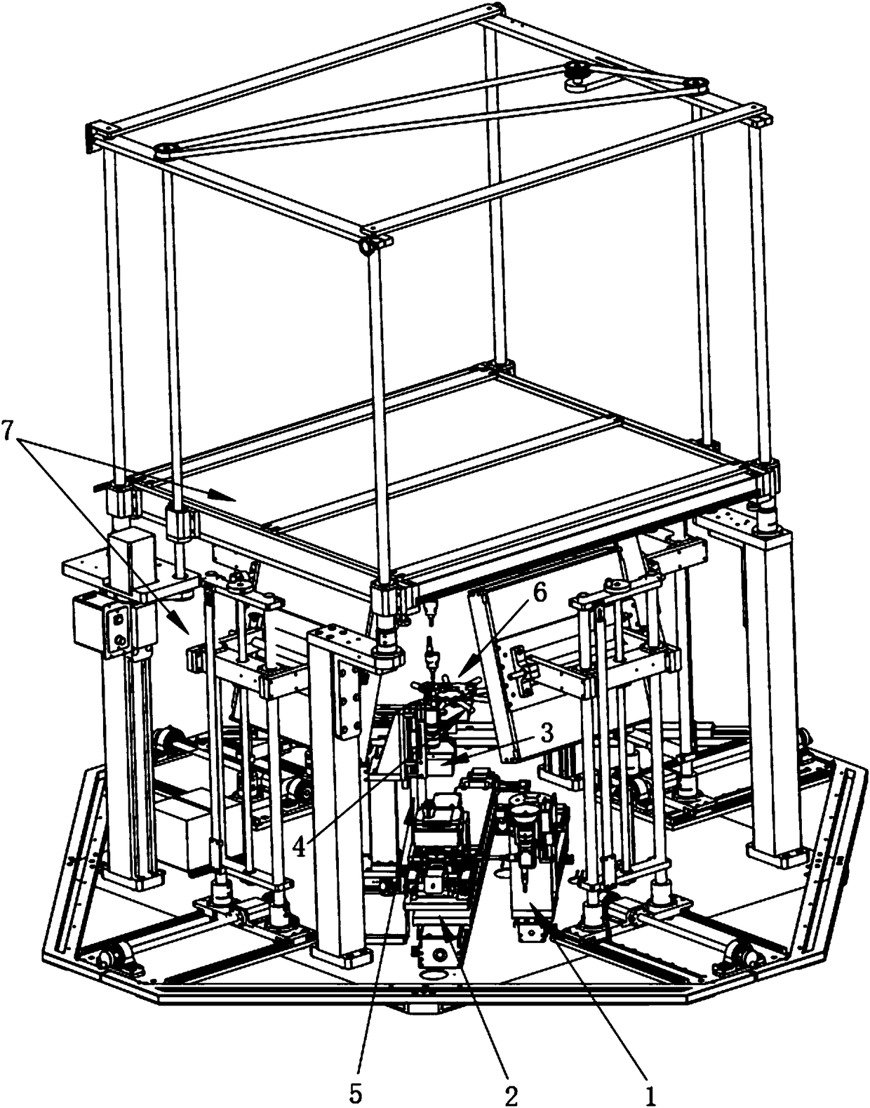
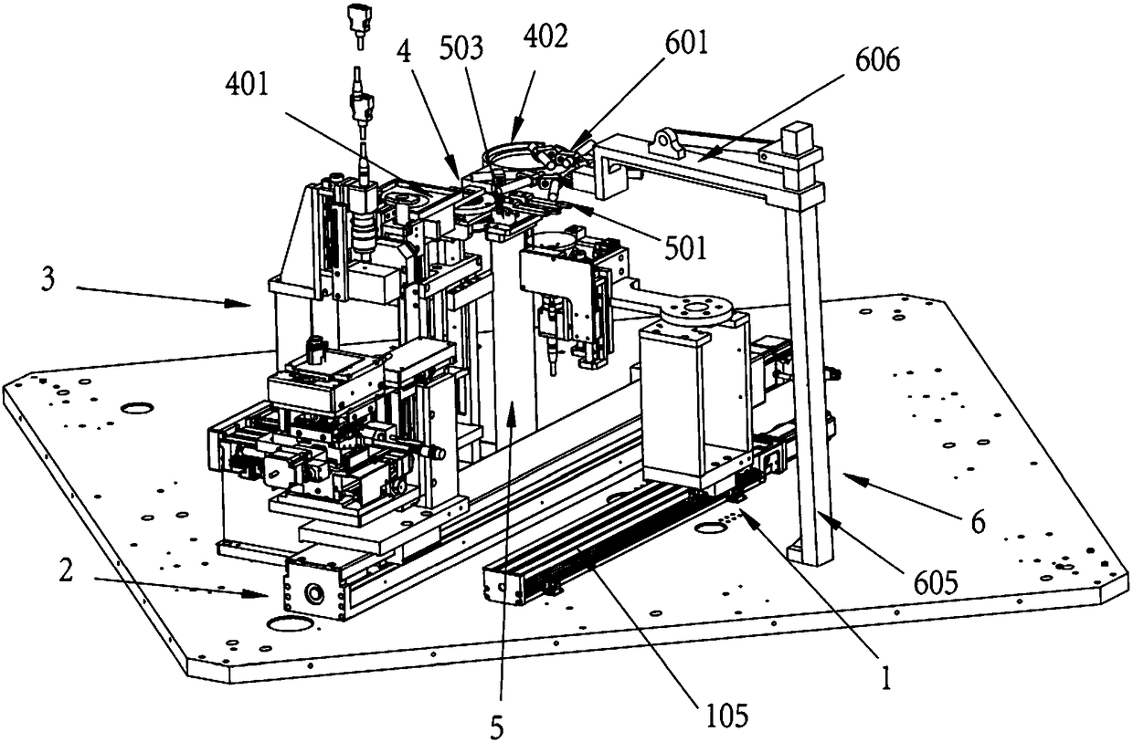
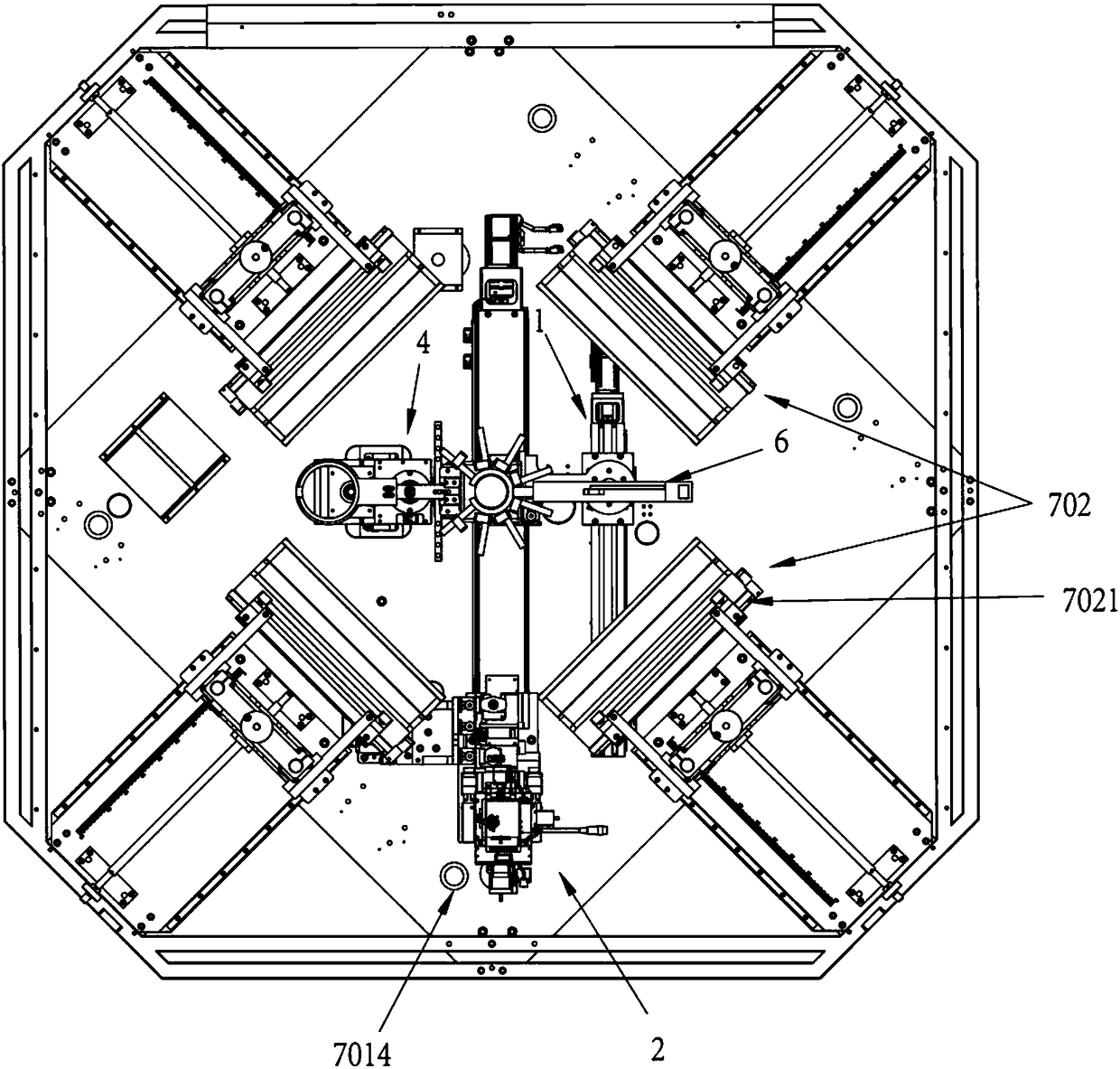
The invention discloses assembly equipment for a camera module group, and the equipment comprises a les module group conveying unit, a chip conveying unit, a glue dispensing unit, a detection unit, amodule group clamping unit and an exposure unit. The equipment is characterized in that the equipment also comprises a light source unit; the light source unit consists of a main light source module and an auxiliary light source module. The invention also discloses a method for assembly a camera module group through the equipment. The equipment can achieve the automatic assembly of various types of camera module group, and especially can provide a big view field environment required by a big view field camera module group. Moreover, the equipment is simple in structure, is high in testing precision, and is high in yield, wherein the yield is 1.5-2 times of the yield of a common machine.

Description

technical field [0001] The invention relates to an assembly device for a camera module, in particular to a device for assembling a camera module with a large field of view. Background technique [0002] Chinese patent 201210277880.8 discloses a camera module test light box. The camera module test light box moves up and down on the test workbench under the drive of the driving device, so as to realize the automatic adjustment of the height of the light source box. According to this patent, the height of the light source is adjusted by moving the light box up and down, and the brightness of the test light source is adjusted accordingly. This kind of device is only suitable for ordinary camera modules, and the test accuracy is low, the output rate is low, and it cannot provide the large field of view required by the camera module. [0003] Chinese patent 201420425552.2 discloses a far and near view test fixture for a mobile phone camera module. The camera module far and near...

Claims


Application Information

Patent Timeline
Patent Type & Authority Applications(China)
IPC IPC(8): G03B43/00G02B7/00H04N5/225
CPCG02B7/00G03B43/00H04N23/00H04N23/50H04N23/55
Inventor 严春琦陈成权方泽陈永明吴炳
Owner NINGBO SUNNY OPOTECH CO LTD
Learn More