Laser curve scale

A laser and ruler technology, applied in the direction of sewing clothes tools, etc., to achieve good practical value, expand the light source structure, improve the effect of laser curve marking positioning technology

Inactive Publication Date: 2018-05-25
顾效源
View PDF0 Cites 1 Cited by
  • Summary
  • Abstract
  • Description
  • Claims
  • Application Information

AI Technical Summary

Problems solved by technology

At present, the shapes of the spot include dots, straight lines, cross lines, and thick lines, etc., all of which are dots or straight

Method used


Image

  • Laser curve scale
  • Laser curve scale
  • Laser curve scale

Examples


Embodiment 1

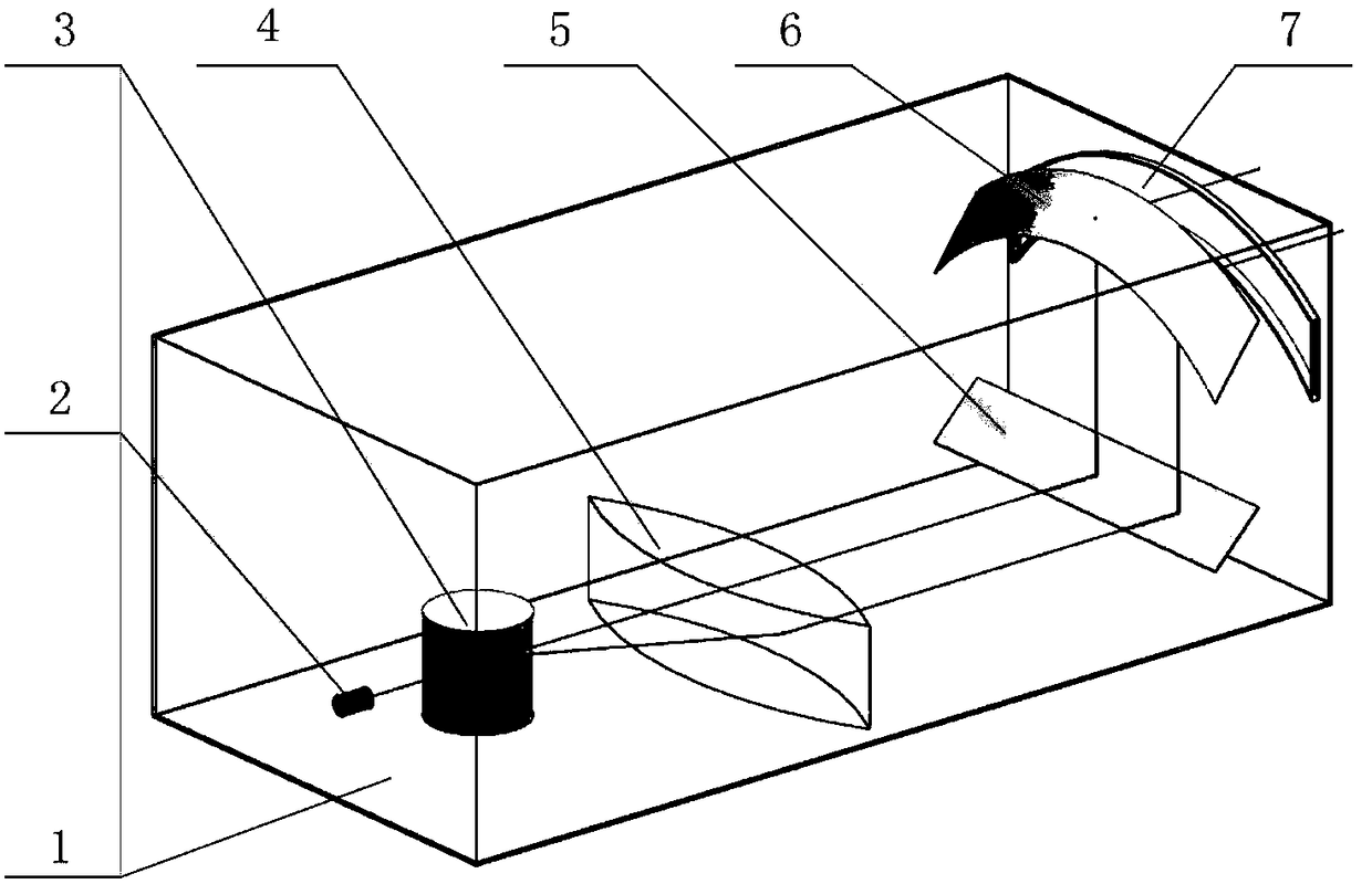
[0036] Such as figure 1 As shown, the laser source 2 is a point light source, and the optical assembly also includes a cylindrical reflector 3, a lens 4 and a plane reflector 5, and the laser light emitted by the point light source is expanded into laser light by the cylindrical reflector 3 The flat sheet light is converted into parallel laser light through the lens 4, and the parallel laser light passes through the plane reflector 5 to change its path, and then is reflected twice by the curved surface reflector 6 to form a ruled curved surface laser. Wherein, the reflective surface of the curved reflector 6 is a cylindrical surface, and a laser is used as a laser source. Therefore, in this embodiment, the laser ruled curved surface emitted from the laser outlet 7 is a cylindrical surface, and the ruled lines are consistent with the direction of the laser light emitted by the laser source 2 . In order to achieve the required accuracy of the ruled curved surface, the curved mi...

Embodiment 2

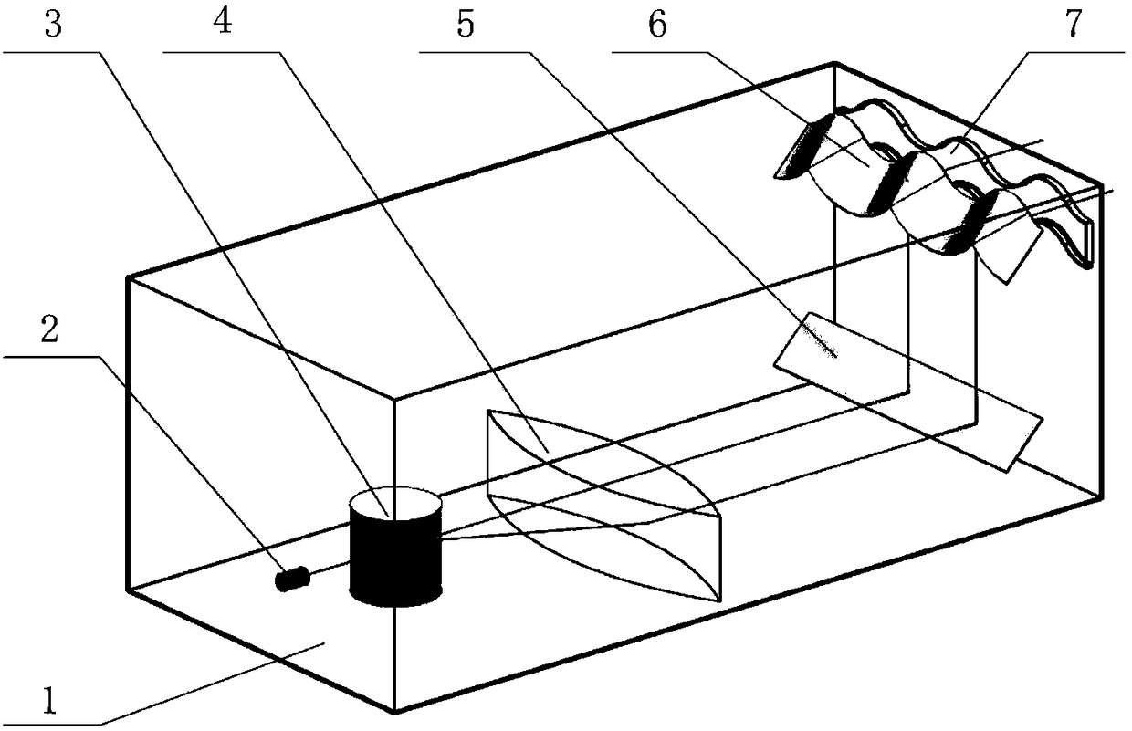
[0038] Such as figure 2 As shown, Embodiment 2 is basically the same as Embodiment 1, except that the reflective surface of the curved mirror 6 is a corrugated surface, so that the ruled curved surface of the laser emitted from the laser outlet 7 is a corrugated surface.

Embodiment 3

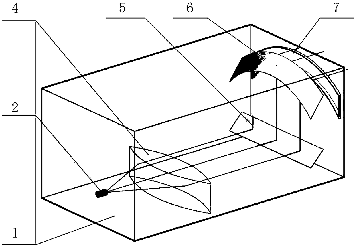
[0040] Such as image 3 As shown, embodiment 3 is basically the same as embodiment 1, the difference is that the cylindrical reflector 3 is removed, and the point light source 2 is directly positioned at the focal point of the lens 4 .


PUM


Abstract

The invention provides a laser curve scale comprising a laser source and an optical assembly, wherein the optical assembly comprises a curved reflector, and laser light emitted by the laser source isreflected by the curved reflector to form a ruled surface laser. The laser curve scale is a ruled surface laser curve scale which is simple in structure, low in device investment, small in light intensity loss and simple to operate, and the laser curve scale has very good practical significance for expanding a laser chip light source structure, simplifying the laser measurement operation and improving a laser scribing process.

Description

technical field [0001] The invention relates to a laser generating device, in particular to a laser generating device for marking line positioning. Background technique [0002] The laser has excellent characteristics such as high brightness, high direction and high monochromaticity. These characteristics ensure that the laser beam can be accurately focused to the focal point, generating thousands of degrees or even tens of thousands of degrees of high temperature and extremely high power density, so that the laser can process almost all materials. The laser sheet light source refers to the use of some instrument to adjust the polarization ratio and linear polarization, so that the light source is scattered at a certain angle to form a larger scattered beam. [0003] Laser sheet light sources are commonly used in the fields of PIV (Particle Imaging Velocimetry) and PLIF (Planar Laser Beam Induced Fluorescence Imaging) multi-field measurements, but currently all planar sheet...

Claims


Application Information

Patent Timeline
IPC IPC(8): A41H1/00
CPCA41H1/00
Inventor 顾效源
Owner 顾效源
Why Eureka
Try Eureka