Ultrasonic transducer device, ultrasonic probe, and ultrasonic apparatus
一种超声波、换能器的技术,应用在超声波换能器器件领域,能够解决难以辨认、超声波图像不明确等问题
- Summary
- Abstract
- Description
- Claims
- Application Information
AI Technical Summary
Problems solved by technology
Method used
Image


Examples
no. 1 approach
[0076] In this embodiment, a characteristic example of an ultrasonic transducer device and a method of manufacturing the ultrasonic transducer device will be described with reference to the drawings. according to Figure 1 to Figure 23 , and the ultrasonic transducer device according to the first embodiment will be described.
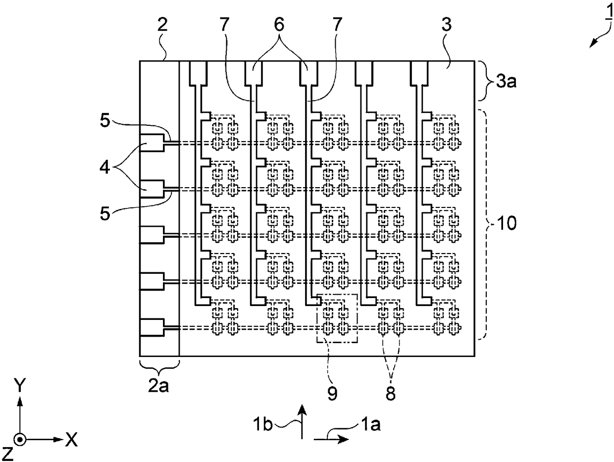
[0077] figure 1 is a schematic plan view showing the configuration of the ultrasonic transducer device. Such as figure 1 As shown, the ultrasonic transducer device 1 includes a first substrate 2 and a second substrate 3 . A manner in which the second substrate 3 overlaps the first substrate 2 is formed.
[0078] The first substrate 2 is rectangular with two adjacent sides orthogonal to each other. The direction in which one side extends is the X direction, and the direction in which the sides adjacent to each other in the X direction extend is the Y direction. Let the thickness direction of the first substrate 2 be the Z direction.
[0079] The l...
no. 2 approach
[0162] Next, use Figure 24 A schematic side sectional view of main parts showing the configuration of the ultrasonic transducer device will be described to describe an embodiment of the ultrasonic transducer device. This embodiment differs from the first embodiment in that a through-hole is provided in a portion of the second substrate 3 facing the ultrasonic element 8 . In addition, descriptions of the same points as those in the first embodiment are omitted.
[0163] That is, according to this embodiment, if Figure 24As shown, in the ultrasonic transducer device 44, the first substrate 2 and the second substrate 45 are overlapped. Furthermore, in the second substrate 45 , a through-hole 46 is provided at a portion facing the ultrasonic element 8 . The ultrasonic wave 33 transmitted in the +Z direction by the ultrasonic element 8 can travel in the +Z direction through the through-hole 46 .
[0164] Then, the reflected wave 34 traveling toward the ultrasonic element 8 fr...
no. 3 approach
[0166] Next, use Figure 25 and Figure 26 , an embodiment of the ultrasonic transducer device will be described. Figure 25 It is a schematic side sectional view of main parts showing the configuration of the ultrasonic transducer device. Figure 26 It is a schematic plan view of main parts showing the configuration of the ultrasonic transducer device. This embodiment differs from the first embodiment in that wiring corresponding to the second wiring 7 is provided inside the first chassis 11 . In addition, descriptions of the same points as those in the first embodiment are omitted.
[0167] That is, according to this embodiment, if Figure 25 As shown, the ultrasonic transducer device 50 includes a base substrate 51 . The ultrasonic elements 8 constituting the ultrasonic element unit 9 are arranged side by side on the base substrate 51 . The ultrasonic elements 8 on the left side in the figure are the first element 8a and the third element 8c, and the ultrasonic elemen...
PUM
 Abstract
Description
Claims
Application Information
 - R&D
- Intellectual Property
- Life Sciences
- Materials
- Tech Scout
- Unparalleled Data Quality
- Higher Quality Content
- 60% Fewer Hallucinations
Browse by: Latest US Patents, China's latest patents, Technical Efficacy Thesaurus, Application Domain, Technology Topic, Popular Technical Reports.
© 2025 PatSnap. All rights reserved.Legal|Privacy policy|Modern Slavery Act Transparency Statement|Sitemap|About US| Contact US: help@patsnap.com