Permanent magnet suspending stirrer for high-temperature heavy load working condition

A heavy-duty working condition and magnetic levitation technology, which is applied in the direction of mixer accessories, chemical instruments and methods, and dissolution, can solve problems such as shortening the service life of equipment, failure of sliding bearings, and wear of contact surfaces, so as to maintain self-lubricating characteristics and improve parts. The effect of life and contact surface wear is small

Pending Publication Date: 2018-05-25
BAOJI TAIHUA MAGNETIC ELECTROMECHANICAL TECH RES INST CO LTD
View PDF13 Cites 4 Cited by
  • Summary
  • Abstract
  • Description
  • Claims
  • Application Information

AI Technical Summary

Problems solved by technology

On the one hand, this huge sliding friction increases the stirring resistance torque, on the other hand, it accelerates the wear of the contact surface of the sliding thrust bearing, which causes the failure of the agitator and shortens the life of the agitator; Only use equal-length studs and nuts for fastening, because there is a gap between the inner diameter of the cover plate hole and the outer diameter of the equal-length studs, when the stirred tank is running at high temperature, it is very easy to misalign the center hole of the upper and lower cover plates. The stirring shaft system is tilted, resulting in uneven contact of the sliding bearing contact surface, which leads to contact surface wear and agitator failure; fourth, the wear-resistant coating itself has limited ability to adapt to high temperature and heavy load conditions. After a certain period of operation, it will Gradually thinning, or even falling off, leading to failure of sliding bearings, frequent equipment failures, and shortened equipment life
In addition, the high price of imported equipment and harsh after-sales service conditions also greatly increase the process cost

Method used


Image

  • Permanent magnet suspending stirrer for high-temperature heavy load working condition

Examples


Embodiment Construction

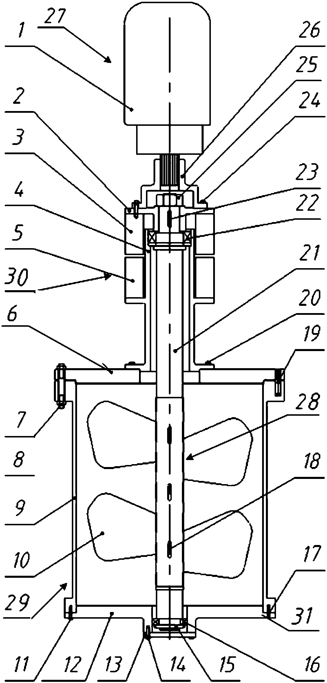
[0020] In order to make the technical means realized by the present invention, creative features and reach purpose and effect easy to understand, the following in conjunction with the appended figure 1 Specific embodiments of the present invention will be described in detail. It should be understood that the specific embodiments described here are only used to illustrate and explain the present invention, and are not intended to limit the present invention.

[0021] The components used in the following examples are commercially available unless otherwise specified. In the present invention, in the absence of a detailed description, the orientation or positional relationship indicated by "up, down, left, right, front, back, vertical, horizontal, inside, outside" described in the content is based on The orientations or positional relationships shown in the drawings are only for the convenience of describing the present invention and simplifying the description, rather than indi...


PUM


Abstract

The invention provides a permanent magnet suspending stirrer for a high-temperature heavy load working condition, which comprises a driving device, a stirring axis structure, a stirring kettle and a permanent magnet suspending component; the stirring kettle comprises a stirring kettle body, an upper cover plate of the stirring kettle fixed at the upper end opening of the stirring kettle body, anda lower cover plate of the stirring kettle fixed at the lower end opening of the stirring kettle body; the stirring axis structure comprises a bearing base and a stirring axis; the bearing base is fixed at the upper part of the upper cover plate of the stirring kettle, the upper and lower ends of the stirring axis are supported at the inner part of the bearing base and the center hole of the lowercover plate of the stirring kettle through a roil bearing I and a roll bearing II; the upper end of the stirring axis is fixed with a lower connecting flange fixedly connected with the driving device, and the permanent magnet suspending component is arranged between the lower connecting flange and an outer step plate of the bearing base. The stirring axis structure can realize non-contact suspending location axially through mutually exclusive magnetic force of the permanent magnet suspending component, and adopts roll bearing location on a radical direction; thus the problems of quick wear ofaxis shoulder end face of the existing device, big resistance torque, and need of big power motor, and others are solved.

Description

technical field [0001] The invention belongs to the technical field of stirrers, and in particular relates to a permanent magnetic levitation stirrer used in high-temperature and heavy-load working conditions. Background technique [0002] Many processing techniques in nuclear power, petrochemical and pharmaceutical industries require agitators to operate under conditions of high temperature, heavy load, and dry friction of bearings. Due to the harsh operating conditions, this kind of agitator for high-temperature and heavy-duty working conditions cannot be manufactured by domestic companies at present, and can only rely on imports, and imported agitators also have short service life, high failure rate, expensive, High after-sales service costs and many other deficiencies. The main technical features of the imported agitator for high-temperature and heavy-duty working conditions are: 1. The radial positioning of the stirring shaft adopts the sliding bearing method, which is...

Claims


Application Information

Patent Timeline
Patent Type & Authority Applications(China)
IPC IPC(8): B01F13/08B01F15/00
CPCB01F33/452B01F35/51
Inventor 赵克中茆军兵闫雪兰韩爱国李成军杜海宽马斗军修振海孙婷马田礼张严龙
Owner BAOJI TAIHUA MAGNETIC ELECTROMECHANICAL TECH RES INST CO LTD
Why Eureka
Try Eureka