Plastic mixing mechanism for plastic processing machine

A technology for processing machinery and plastics, which is applied in the field of plastic mixing mechanisms and can solve problems such as uneven mixing

Inactive Publication Date: 2018-05-25
刘辉
View PDF7 Cites 3 Cited by
  • Summary
  • Abstract
  • Description
  • Claims
  • Application Information

AI Technical Summary

Problems solved by technology

[0003] In order to overcome the shortcomings of the above-mentioned prior art, the present invention has produced a plastic mixing mechanism for plastic processing machinery, which is used to solve the problem of uneven mixing caused by the mixing of larger particles and smaller particles in the components.

Method used


Image

  • Plastic mixing mechanism for plastic processing machine

Examples


Embodiment Construction

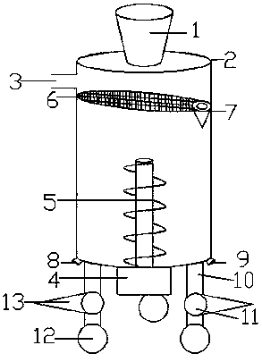
[0011] A plastic mixing mechanism for plastic processing machinery, including a feed hopper 1, a box body 2, a water inlet 3, an axial motor 4, a spiral blade 5, an adjustable screen 6, a cone crusher 7, and a discharge hopper 8 , water outlet 9, support frame 10, bearing 11, roller 12, tapered support 13, box body 2 is cylindrical, feed inlet 1 is arranged on the center position of the top of box body 2 and is fixedly connected with box body 2, The water inlet 3 is arranged on the upper end of the left side of the box body 2, the axial motor 4 is arranged under the box body 2, and the spiral blade 5 is arranged on the center position of the bottom of the box body 2 and is fixedly connected with the axial motor 4, which can The adjustable screen 6 is arranged between the water inlet 3 and the spiral blade 5. The adjustable screen 6 is elliptical and inclined at an angle of 30-60 degrees inside the box 2 and is closely combined with the inner surface of the box 2. The conical T...


PUM

PropertyMeasurementUnit
angleaaaaaaaaaa

Abstract

The invention discloses a plastic mixing mechanism for a plastic processing machine. The plastic mixing mechanism comprises a feeding hopper, a box, a water inlet, an axial motor, a spiral blade, an adjustable screen mesh, a cone crusher, a discharging hopper, a water outlet, supporting frames, bearings, rollers and a conical support. When raw material components in the feeding hopper enter the box, the small-particle components fall onto the bottom of the box, and the large-particle components fall onto the adjustable screen mesh. Due to the fact that the adjustable screen mesh has a certaininclination angle, the large-particle components can roll down along the inclined face of the adjustable screen mesh into the cone crusher connected with the tail end of the adjustable screen mesh, and the large-particle components can be ground into small-particle components through the cone crusher. The ground components flow out of the bottom of the cone crusher, and the ground components and other component raw materials are mixed and stirred together by being mixed by the spiral blade. The plastic mixing mechanism is reasonable in design, easy to operate and high in practicality.

Description

technical field [0001] The present invention relates to the field of plastic processing machinery, in particular to a plastic mixing mechanism for plastic processing machinery. Background technique [0002] The mixer is composed of a horizontally rotating container and rotating vertical mixing blades. When the molding material is stirred, the container turns to the left and the blade turns to the right. Due to the effect of countercurrent, the movement direction of the particles of the molding material crosses and interacts with each other. The chance of contact increases, the extrusion force of the countercurrent mixer is small, the calorific value is low, the stirring efficiency is high, and the mixing is relatively uniform. The mixer is suitable for mixing powdery resin molding materials, and can also be used for mixing liquid resin molding materials. On this basis, the mouldboard mixer has been improved. The material pot in its structure is basically the same as that o...

Claims


Application Information

Patent Timeline
Patent Type & Authority Applications(China)
IPC IPC(8): B29B7/14B29B7/22B29B13/10B29B7/94
CPCB29B7/14B29B7/22B29B7/94B29B13/10
Inventor 刘辉
Owner 刘辉
Why Eureka
Try Eureka