
Laser positioning distance measuring tool

A technology of laser positioning and tools, which is applied in the direction of active optical measuring devices, measuring devices, measuring instruments, etc., can solve the problems of expensive debugging, large equipment volume, and large parameter errors, and achieve low production costs, high measurement accuracy, and easy operation. convenient effect

Inactive Publication Date: 2018-05-25
HUBEI DAYUN AUTOMOBILE
View PDF0 Cites 9 Cited by
  • Summary
  • Abstract
  • Description
  • Claims
  • Application Information

AI Technical Summary

Problems solved by technology

[0003] At present, the measurement methods of technical parameters of commercial vehicles include tape measurement and vehicle outline size detection system. Among them, tape measurement is simple to operate, low in efficiency, and the larger the size, the larger the parameter error, and it is only used when the accuracy is not high. Vehicles The measurement accuracy of the outer dimension detection system is high, but the equipment used in it is large in size and complex in structure, and needs to be installed and used in a professional site. The equipment, installation and commissioning are expensive and there are few measurable parameter items. To meet the requirements of parameter measurement, the present invention provides a laser positioning and ranging tool based on laser positioning and ranging technology

Method used


Image

  • Laser positioning distance measuring tool
  • Laser positioning distance measuring tool
  • Laser positioning distance measuring tool

Examples


Embodiment Construction

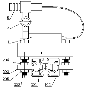
[0019] Such as figure 1 , figure 2 , image 3 and Figure 4 As shown, a laser positioning and ranging tool is characterized in that: it includes a precision sliding guide rail 1, a left sliding seat 2 and a right sliding seat 3 arranged horizontally; the structure of the precision sliding guide rail 1 is: including a connecting slide rail 101, a left sliding The rail 102 and the right slide rail 103, the left slide rail 102 and the right slide rail 103 are respectively slidingly connected with the left and right ends of the connecting slide rail 1, that is, the shape of the four connecting slide rails 101 is consistent with that of the left slide rail 102 and the right slide rail 103. The shapes of the inner chambers at the four corners match; the left slider 2 and the right slider 3 are slidingly connected with the left slider 102 and the right slider 103 respectively; the left slider 2 and the right slider 3 have the same structure, and the left slider 2 The structure is...


PUM


Abstract

The invention relates to a laser positioning distance measuring tool. The laser positioning distance measuring tool comprises a precise sliding guide rail, a left sliding seat and a right sliding seatwhich are transversely arranged, wherein the left sliding seat and the right sliding seat are respectively in sliding connection with left and right ends of the precise sliding guide rail, a right end of a top surface of the left sliding seat is provided with a laser distance measuring instrument, one side of the left sliding seat is provided with a vertical left laser lamp, a left end of the topsurface of the left sliding seat is provided with a left power supply module, the left laser lamp is connected with the left power supply module, a left end of a top surface of the right sliding seatis provided with a right power supply module, one side surface of the right power supply module opposite to the laser distance measuring instrument is provided with a laser reflection board, one sideof the right sliding seat is provided with a vertical right laser lamp, the right laser lamp is connected with the right power supply module, laser emission ends of the left laser lamp and the rightlaser lamp are arranged in the same direction, and an interval between the left laser lamp and the right laser lamp is equal to an interval between the laser distance measuring instrument and the laser reflection board. The laser positioning distance measuring tool has advantages of simple structure, convenient operation, low production cost and high measurement precision.

Description

technical field [0001] The invention belongs to the technical field of vehicle parameter measurement, and in particular relates to a laser positioning and ranging tool. Background technique [0002] The technical parameters of the complete vehicle are important parameters for vehicle research and development, trial production and testing, and vehicle announcements. Accurate measurement of the technical parameters of the complete vehicle is of great significance in shortening the test and debugging cycle, reducing test costs, and improving control accuracy. [0003] At present, the measurement methods of technical parameters of commercial vehicles include tape measurement and vehicle outline size detection system. Among them, tape measurement is simple to operate, low in efficiency, and the larger the size, the larger the parameter error, and it is only used when the accuracy is not high. Vehicles The measurement accuracy of the outer dimension detection system is high, but t...

Claims


Application Information

Patent Timeline
Patent Type & Authority Applications(China)
IPC IPC(8): G01S17/08G01C15/00
CPCG01S17/08G01C15/002
Inventor 王强曹纯儒董朝闻张涛张元兵敖娜娜王勇尹丽
Owner HUBEI DAYUN AUTOMOBILE
Learn More