
Smart express cabinet and using method thereof.

An intelligent, cabinet-based technology, applied to coin-operated equipment for distributing discrete items, coin-operated equipment for distributing discrete items, instruments, etc., can solve the problem of difficult control of space fragmentation in express cabinets and express Large height differences, frequent express access and other issues, to achieve real-time background interaction and optimize storage space

Active Publication Date: 2018-05-25
XIAMEN UNIV TAN KAH KEE COLLEGE
View PDF6 Cites 21 Cited by
  • Summary
  • Abstract
  • Description
  • Claims
  • Application Information

AI Technical Summary

Problems solved by technology

According to the current implementation method, the size of each grid in the express cabinet is generally a fixed height, and the express access is frequent, the number of express delivery is large, and the height of the express delivery is large. The main problems of the intelligent express cabinet are: (1) space utilization Insufficient, the space in the express cabinet cannot be reasonably allocated according to the height of the express delivery; (2) The storage space of the express cabinet is difficult to manage, and it is difficult to control the fragmentation of the space in the express cabinet due to the large space occupied by small express delivery; (3) The express access is not enough Intelligent, the courier often needs to classify the courier based on experience, and then store the corresponding courier according to the size of the space in the courier cabinet

Method used


Image

  • Smart express cabinet and using method thereof.
  • Smart express cabinet and using method thereof.
  • Smart express cabinet and using method thereof.

Examples


Embodiment Construction

[0055] The content of the present invention will be described in detail below in conjunction with the accompanying drawings and embodiments of the description:

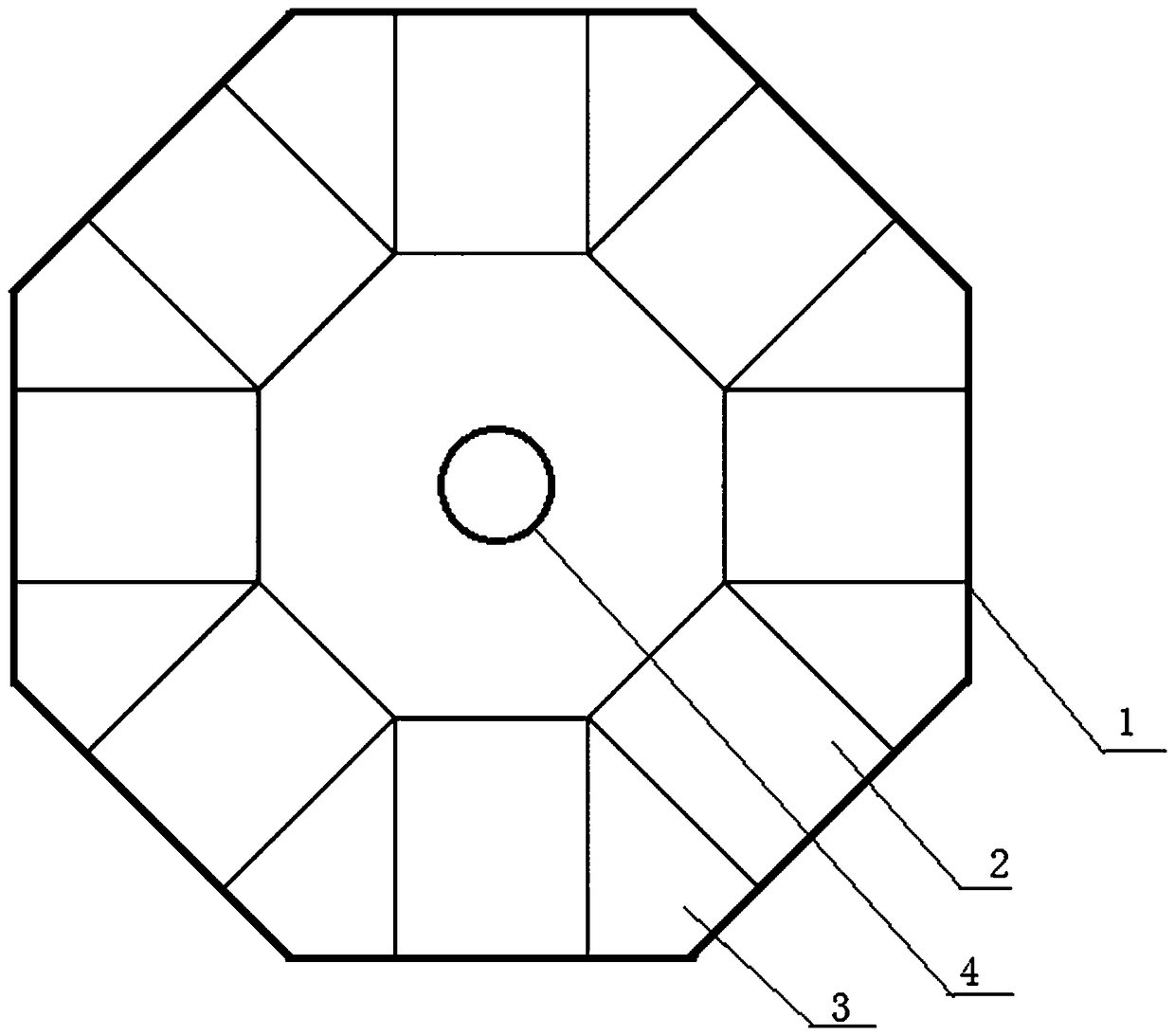
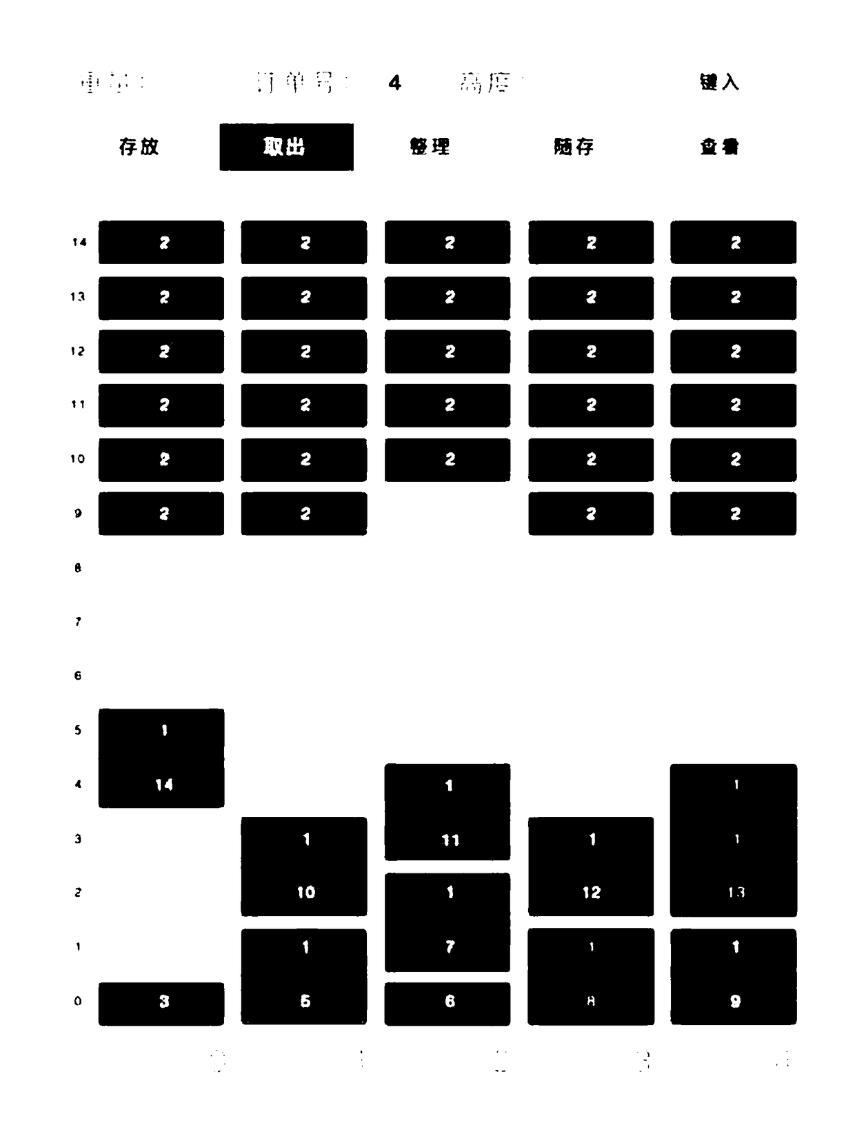
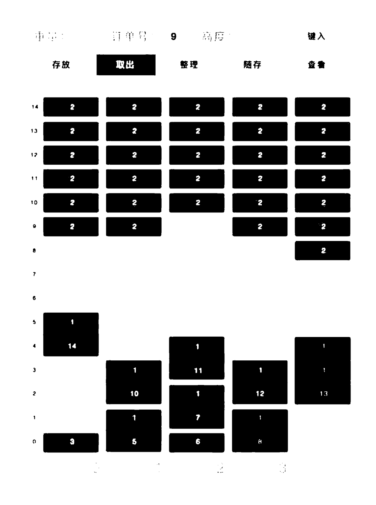
[0056] Such as Figure 1-4 As shown, an intelligent express cabinet includes a cabinet body 1, a tray 2, a plug-in column 3 arranged inside the cabinet body for supporting the tray, a manipulator moving device 4, a scanning device and a main control machine; the cabinet body 1 is a regular octagonal prism Body structure, the interior is a cavity; one side of the cabinet body 1 is used as a cabinet door, and the cabinet door is provided with an article access port 5;

[0057]The board column 3 is located between two adjacent sides of the cabinet body 1, and the opposite sides of the two adjacent board columns are respectively provided with evenly distributed horizontal grooves 6; The side of the cabinet body of the cabinet door forms a row of storage spaces, which are divided into a plurality of basic units by horizon...


PUM


Abstract

The invention relates to a smart express cabinet and a using method thereof. The express cabinet comprises a cabinet body, trays, inserting plate columns arranged inside the cabinet body and used forsupporting the trays, a mechanical hand moving device, a scanning device and a main control machine. The cabinet body is of a regular prismatic structure and is internally provided with a cavity. Oneside of the cabinet body serves as a cabinet door, and the cabinet door is provided with an article access port. The inserting plate columns are located between two adjacent side faces of the cabinetbody, and the opposite side faces of two adjacent inserting plate columns are provided with evenly-distributed horizontal grooves respectively. The trays are inserted into the horizontal grooves and are perpendicular to the side of the cabinet body, and a plurality of height-adjustable storage compartments are formed by changing the insertion positions of the trays to provide physical storage locations for stored articles. The mechanical hand moving device is connected with a main control computer and used to move the trays. The scanning device is mounted at the position of the article accessport and used to obtain specifications of a stored article. The smart express cabinet achieves full-automatic processing after express articles enter the express cabinet without manual intervention ofthe storage location, and a storage space is automatically adjusted and optimized.

Description

technical field [0001] The invention relates to the technical field of intelligent express cabinets, in particular to an intelligent express cabinet and a method for using the same. Background technique [0002] With the frequent use of smart express cabinets, the problems of smart express cabinets have become increasingly prominent. According to the current implementation method, the size of each grid in the express cabinet is generally a fixed height, and the express access is frequent, the number of express delivery is large, and the height of the express delivery is large. The main problems of the intelligent express cabinet are: (1) space utilization Insufficient, the space in the express cabinet cannot be reasonably allocated according to the height of the express delivery; (2) The storage space of the express cabinet is difficult to manage, and it is difficult to control the fragmentation of the space in the express cabinet due to the large space occupied by small exp...

Claims


Application Information

Patent Timeline
Patent Type & Authority Applications(China)
IPC IPC(8): G07F17/12G07F11/00
CPCG07F11/00G07F17/12Y02P90/02
Inventor 郭一晶高凤强邱义纪艺娟魏雅君李雄锶潘登峰李雄雄苏鸿宏
Owner XIAMEN UNIV TAN KAH KEE COLLEGE
Learn More