
Crushing assembly for sludge crusher and construction method thereof

A crusher and sludge technology, which is applied in sludge treatment, chemical instruments and methods, water/sludge/sewage treatment, etc., can solve the problems of increased difficulty, poor sustainability, and blocked equipment, so as to promote crushing or shearing , a wide range of applications, easy to produce effects

Active Publication Date: 2018-05-29
广州正晟科技有限公司
View PDF6 Cites 1 Cited by
  • Summary
  • Abstract
  • Description
  • Claims
  • Application Information

AI Technical Summary

Problems solved by technology

However, there are many deficiencies in these crushing equipment, one of which is that the equipment is prone to be blocked by sludge blocks during the sludge crushing process, and the size of the crushed small blocks is not uniform, which makes the operation of the equipment difficult. Poor sustainability and affects the stability of sludge crushing, thus increasing the difficulty of subsequent treatment, especially in the drying process it is difficult to further reduce the moisture content of the crushed sludge small pieces
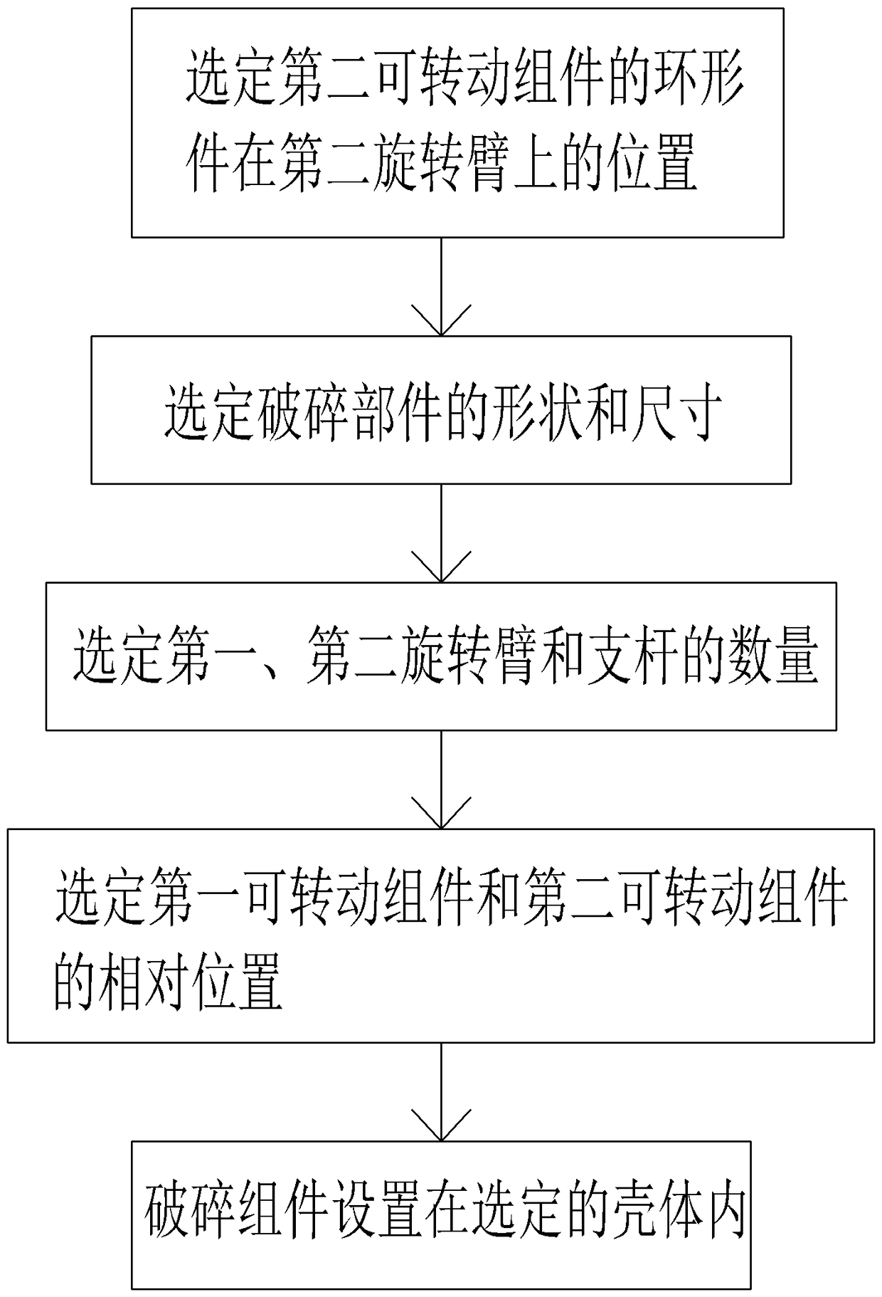
For this reason, a kind of crushing process proposed by the applicant is stable and can obtain the vertical crusher of the sludge fragment of uniform particle size that can alleviate or avoid these problems, yet, there is a defective in this vertical crusher is for Sludge blocks with different moisture contents can only be crushed or sheared by one type of crushing component, therefore, it is necessary to propose a crushing component based on different moisture content and adapting to different environmental conditions and a method of composing such a crushing component

Method used


Image

  • Crushing assembly for sludge crusher and construction method thereof
  • Crushing assembly for sludge crusher and construction method thereof
  • Crushing assembly for sludge crusher and construction method thereof

Examples


Embodiment Construction

[0017] It should be understood that the drawings herein are not drawn to scale in order to clearly show the contents thereof, and the same or similar reference numerals indicate the same or similar parts or parts.

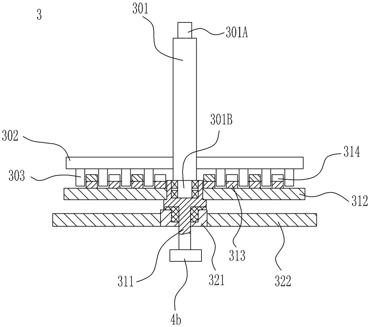
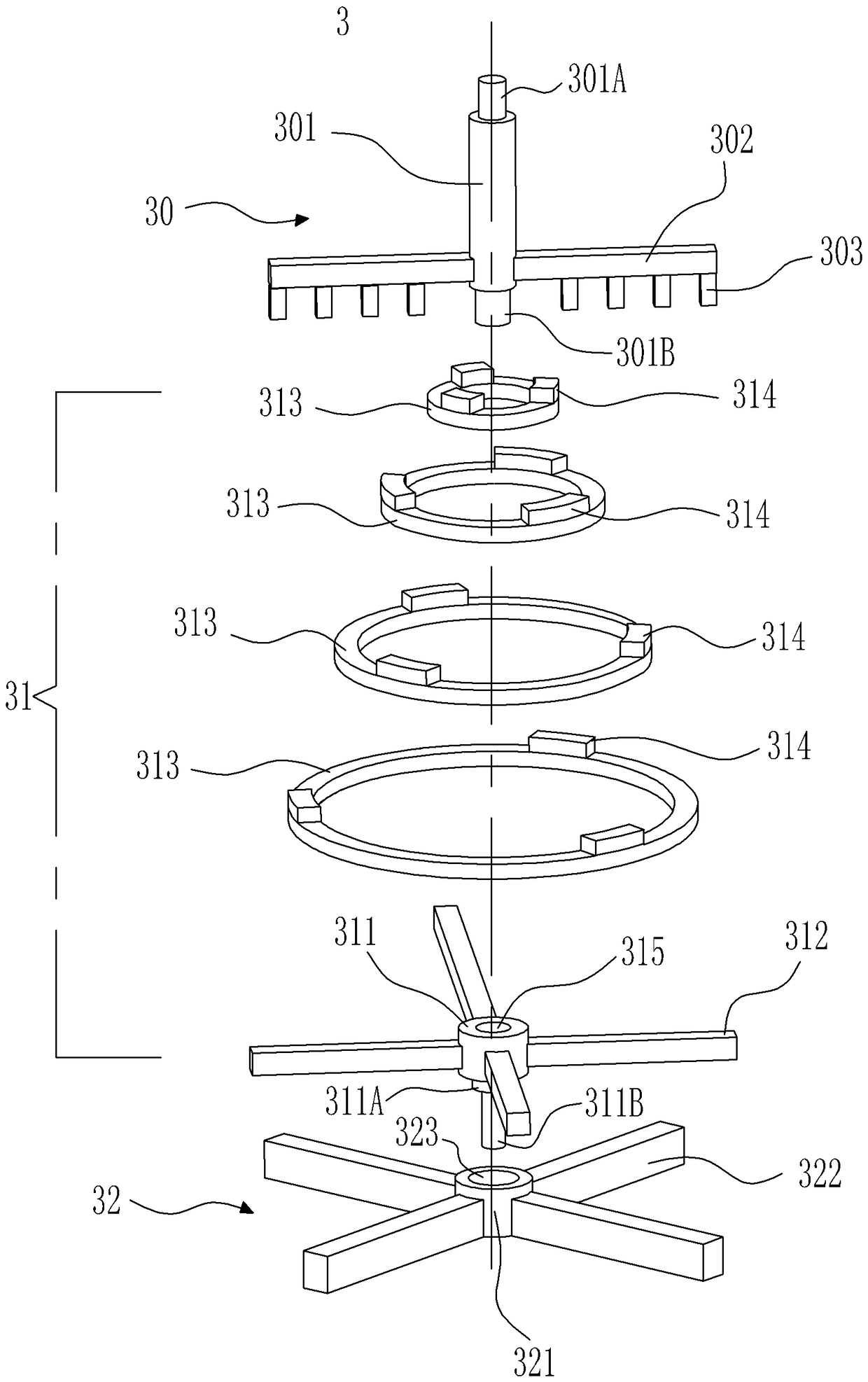
[0018] figure 1 A vertical crusher is schematically shown in a perspective view, wherein a preferred embodiment of the crushing assembly for crushing sludge lumps according to the invention is used in the vertical crusher. figure 2 shown in cross-sectional view figure 1 Broken components in. As shown in the figure, a crushing assembly 3 for crushing sludge lumps is arranged in the casing 2 of the vertical crusher 1 . The casing 2 is generally arranged vertically, and may include a cylinder body 202 and a top cover 201 located at the upper end of the cylinder body, wherein the bottom of the cylinder body 202 is opened downward. In addition, the housing 2 can be constructed in other forms, for example, the cylinder body 202 and the top cover 201 of the housing 2 ...


PUM


Abstract

The invention relates to a crushing assembly which is used in a vertical sludge crusher. The crushing assembly is arranged in a vertical shell body and includes a first rotatable assembly, a second rotatable assembly and a fixing assembly. The first rotatable assembly is provided with a first rotating shaft, a first whirling arm which extends outward from the lower end of the first rotatable assembly and crushing parts which are arranged on the first rotating arm. The second rotatable assembly is provided with a second rotating shaft, a second whirling arm which extends outward from the secondwhirling arm and annular pieces which are arranged on the second whirling arm. The fixing assembly is provided with a center column and a support rod which extends outward from the center column. Thesecond whirling column is arranged between the first whirling assembly and the fixing assembly, the lower end of the second rotating shaft is rotatably arranged in an axle hole of the center column and extends out of the axle hole, and the crushing assembly and the annular pieces are arranged in a staggered distribution mode. The invention further relates to a method of forming the crushing assembly for the vertical sludge crusher.

Description

technical field [0001] The present invention relates to the field of sludge drying, and relates to a crushing assembly for a sludge crusher, especially a crushing assembly for crushing sludge blocks in a vertical sludge crusher and the method for constructing the crushing assembly method. Background technique [0002] The sludge drying process usually requires dehydration of liquid sludge to treat the liquid sludge into solid sludge. Dehydration treatment generally uses solid-liquid separation equipment to separate solid-liquid from the sludge, and the dehydrated sludge forms a larger block with a certain water content. In order to facilitate subsequent landfilling, solidification or drying of the sludge block For chemical treatment, larger sludge blocks need to be broken into smaller blocks. Compared with other solid-liquid separation equipment, the sludge block with high solid content can be obtained by using the filter press, and its water content is about 75%~40%, and ...

Claims


Application Information

Patent Timeline
Patent Type & Authority Applications(China)
IPC IPC(8): B02C18/10B02C18/18C02F11/12
CPCC02F11/121B02C18/10B02C18/18
Inventor 谭玮
Owner 广州正晟科技有限公司
Learn More