
Plate material trimming and grinding device

An edge-cutting and board-type technology is applied in the field of edge-cutting and grinding devices for board materials, which can solve the problems of manual grinding, high work intensity and low production efficiency, and achieve the effect of preventing relative displacement, improving grinding effect and facilitating grinding.

Active Publication Date: 2018-05-29
JIANGSU JINYANG MACHINERY
View PDF6 Cites 9 Cited by
  • Summary
  • Abstract
  • Description
  • Claims
  • Application Information

AI Technical Summary

Problems solved by technology

At present, the grinding of such plates is generally done manually, usually with a file or a plate grinder. However, these grinding methods are relatively backward, and there are problems of high work intensity, low production efficiency, and poor dimensional accuracy.
The present invention is proposed mainly to solve the problems of manual grinding, low production efficiency, and poor dimensional accuracy.
[0003] The existing plate grinding device has the following deficiencies: 1. When grinding the material, a grinding mechanism is set to move around the material, which is equivalent to grinding a material. The grinding mechanism needs to rotate for a cycle, which takes a long time , low efficiency; 2. The material is directly placed on the upper surface of the conveyor belt, and then it is inconvenient to be lifted and fixed by the hydraulic cylinder, which leads to relative displacement between the material and the device during the grinding process, and the grinding mechanism will damage the material

Method used


Image

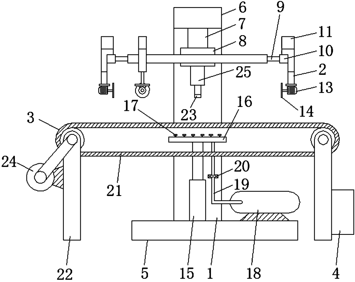
  • Plate material trimming and grinding device
  • Plate material trimming and grinding device
  • Plate material trimming and grinding device

Examples


Embodiment Construction

[0022] The following will clearly and completely describe the technical solutions in the embodiments of the present invention with reference to the accompanying drawings in the embodiments of the present invention. Obviously, the described embodiments are only some, not all, embodiments of the present invention. Based on the embodiments of the present invention, all other embodiments obtained by persons of ordinary skill in the art without making creative efforts belong to the protection scope of the present invention.

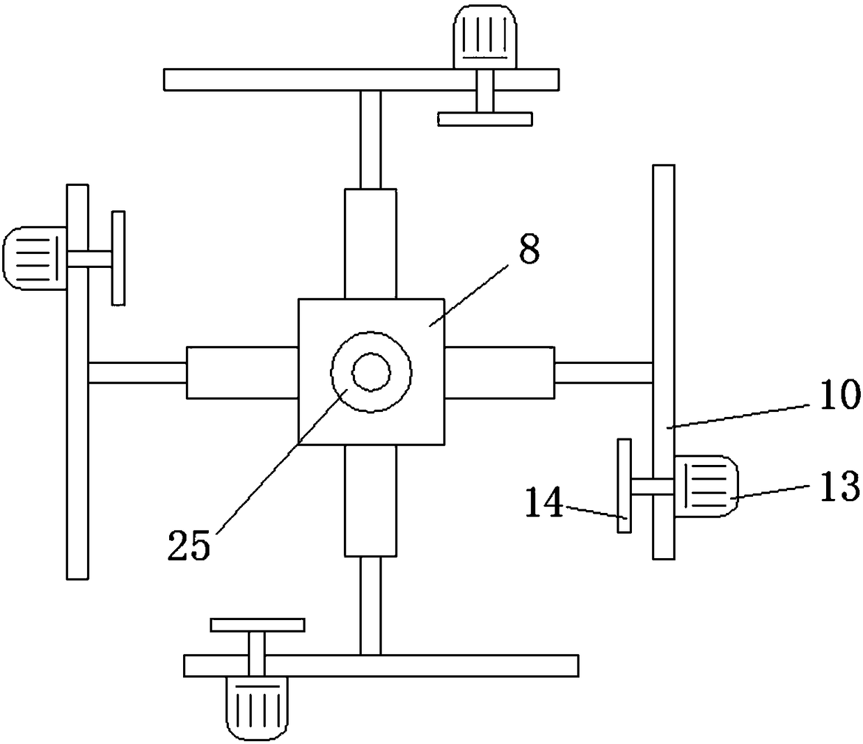
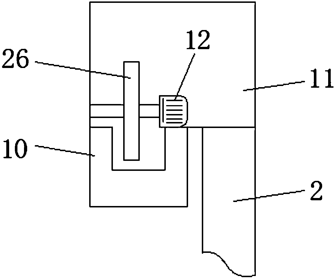
[0023] see Figure 1-3 , the present invention provides a technical solution: a device for trimming and grinding board materials, including a mounting frame 1, a grinding mechanism 2, a conveying mechanism 3 and a control box 4, the lower end of the mounting frame 1 is fixedly provided with a base 5, the The upper end of the mounting frame 1 is fixedly provided with a cantilever 6, and the lower surface of the cantilever 6 away from the end of the mounting fra...


PUM


Abstract

The invention discloses a plate material trimming and grinding device. The device comprises a mounting frame, grinding mechanisms, a conveying mechanism and a control box; a base is fixedly arranged at the lower end of the mounting frame, and a cantilever is fixedly arranged at the upper end of the mounting frame; a connecting rod is fixedly arranged on the lower surface of the end, far away froma mounting seat, of the cantilever, and a mounting table is fixedly arranged at the lower end of the connecting rod; first hydraulic cylinders are arranged in the middles of the outer sides of the mounting table, and guide rails are arranged at the ends of telescopic rods of the first hydraulic cylinders; the grinding mechanisms are composed of machine boxes and first motors, rolling wheels are installed on one sides of the lower ends of the outer parts of the machine boxes, and the lower ends of the rolling wheels are connected with the guide rails; and second motors are arranged inside the machine boxes, the output shaft ends of the second motors are connected with rotating shafts where the rolling wheels are located, and the first motors are fixedly connected with the outer walls of themachine boxes through connecting rods. According to the plate material trimming and grinding device, edges of plate material can be quickly polished, production efficiency is improved, and the platematerial is effectively prevented from being damaged.

Description

technical field [0001] The invention relates to the field of grinding devices, in particular to a device for trimming and grinding board materials. Background technique [0002] After the sheet is formed or cut, its edges are vertical and sharp and need to be ground to the desired edge shape. At present, the grinding of such plates is generally done manually, usually with a file or a plate grinder. However, these grinding methods are relatively backward, and there are problems of high work intensity, low production efficiency, and poor dimensional accuracy. The present invention is proposed mainly to solve the problems of manual grinding, low production efficiency, poor dimensional accuracy and the like. [0003] The existing plate grinding device has the following deficiencies: 1. When grinding the material, a grinding mechanism is set to move around the material, which is equivalent to grinding a material. The grinding mechanism needs to rotate for a cycle, which takes a ...

Claims


Application Information

Patent Timeline
Patent Type & Authority Applications(China)
IPC IPC(8): B24B9/02B24B41/06B24B41/02
CPCB24B9/02B24B41/02B24B41/06
Inventor 陈俞英
Owner JIANGSU JINYANG MACHINERY
Learn More