Cold storage mechanism

A technology of cold storage and reducer, which is applied in the direction of storage, transportation and packaging, etc. It can solve the problems of difficult to find the location of different refrigerated products in the cold storage, and the inconvenience of using the cold storage, so as to improve the space utilization rate and realize the effect of space utilization

Pending Publication Date: 2018-05-29
江苏智维自动化设备有限公司
View PDF0 Cites 4 Cited by
  • Summary
  • Abstract
  • Description
  • Claims
  • Application Information

AI Technical Summary

Problems solved by technology

[0003] The technical problem to be solved by the present invention is: in order to solve the problem that refrigerated products generally rely on manual transportation to enter and exit the cold storage in the prior art, it will bring great inconvenience to the use of the cold storage, and it is not easy to find out where different refrigerated products are placed in the cold storage location problem, a refrigerated storage mechanism is now provided

Method used


Image

  • Cold storage mechanism
  • Cold storage mechanism
  • Cold storage mechanism

Examples


Embodiment 1

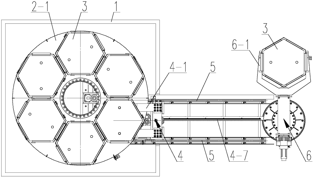
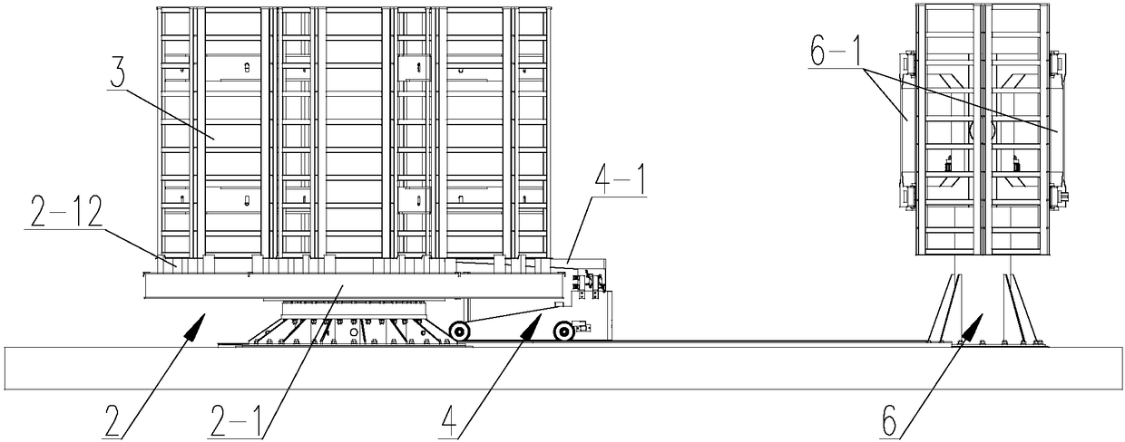
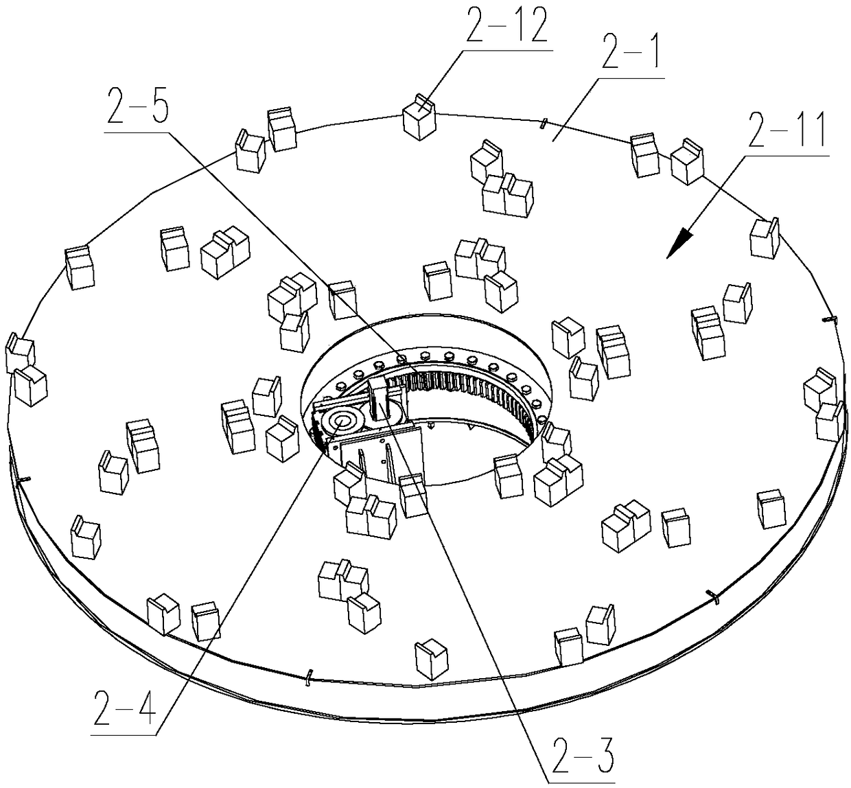
[0031] like figure 1 and 2 As shown, a refrigerated storage mechanism includes a cold storage 1, a rotary storage device 2 located in the cold storage 1, a bucket 3 for storing refrigerated products, and a self-running trolley 4 for transporting the bucket 3 into and out of the cold storage 1 And the guide rail 5 that is used to guide the self-running trolley 4, the rotary storage device 2 includes a turntable 2-1 for placing the material barrel 3 and a power assembly for driving the turntable 2-1 to rotate, and one end of the guide rail 5 is connected from the outside The entrance and exit of the cold storage 1 extend into the cold storage 1. The self-running trolley 4 has a fork 4-1 and a lifting assembly for placing the material barrel 3. The lifting assembly is used to drive the fork 4-1 to rise or fall to achieve Take out or place the bucket 3 on the turntable 2-1.

[0032] like Figure 5 and 9 As shown, the bottom of the bucket 3 is provided with a positioning hole 3...

Embodiment 2

[0042] The difference between embodiment 2 and embodiment 1 is: as figure 1 and 3 As shown, the cross-section of the material barrel 3 is hexagonal, the upper surface of the turntable 2-1 is divided into six storage areas 2-11 for placing the material barrel 3 at equal intervals along its circumferential direction, and the guide rail 5 is located in the cold storage 1 There is a storage station at one end of the car. When the self-running trolley 4 arrives at the storage station along the guide rail 5, the fork 4-1 on the self-running trolley 4 is located on the turntable 2-1 at a storage area 2 closest to the entrance and exit of the cold storage 1. -11, the position of the guide rail 5 relative to the turntable 2-1 is set so that when the self-running trolley 4 moves to the storage station, the innermost outer surface of the barrel 3 on the self-running trolley 4 faces the center of the turntable 2-1, Wherein the hexagonal bucket 6 can facilitate the clamping of the manipul...


PUM


Abstract

The invention relates to the technical field of cold storage, in particular to a cold storage mechanism. The cold storage mechanism comprises a refrigeration house, a rotary type storage device, charging baskets, a self-running trolley and guide rails, wherein the rotary type storage device is located in the refrigeration house, the charging baskets are used for containing cold storage products, the self-running trolley is used for conveying the charging baskets into and out of the refrigeration house, and the guide rails are used for guiding the self-running trolley. The rotary type storage device comprises a rotary disc and a power assembly, wherein the rotary disc is used for containing the charging baskets, the power assembly is used for driving the rotary disc to rotate, one ends of the guide rails extend into the refrigeration house from the outside through an inlet and an outlet of the refrigeration house, the self-running trolley is provided with a fork and a lifting componentwhich are used for containing the charging baskets, and the lifting component is used for driving the fork to ascend or descend, so that the charging baskets are taken out or placed on the rotary disc. According to the cold storage mechanism, the self-running trolley and the charging baskets are used, so that the cold storage products can be automatically fed in and out of the refrigeration house,the positions of the cold storage products in the refrigeration house can be rapidly found, the space utilization rate of the refrigeration house can be improved, and the space utilization of the refrigeration house is optimized.

Description

technical field [0001] The invention relates to the technical field of refrigerated storage, in particular to a refrigerated storage mechanism. Background technique [0002] With the popularization of refrigeration technology, fruits and vegetables, cold drinks, flowers, green plants, tea, medicines, chemical raw materials, electronic instruments, food, dairy products, meat, aquatic products, livestock carcasses, etc. will all be stored in cold storage. Refrigerated products generally rely on manual transportation to enter and exit the cold storage. Due to the large temperature difference between the inside and outside of the cold storage, the form of manual handling will bring great inconvenience to the use of the cold storage, and it is not easy to find the placement of different refrigerated products in the cold storage. s position. Contents of the invention [0003] The technical problem to be solved by the present invention is: in order to solve the problem that refr...

Claims


Application Information

Patent Timeline
Patent Type & Authority Applications(China)
IPC IPC(8): B65G1/12
CPCB65G1/12
Inventor 戴晓峰徐恒王长春黄丹毓张步新
Owner 江苏智维自动化设备有限公司
Why Eureka
Try Eureka