Intelligent pipeline corridor maintenance device with water removing and dredging functions

A technology for maintaining equipment and functions, applied in waterway systems, water supply devices, mechanically driven excavators/dredgers, etc., can solve the problem of reducing the practicability of pipe gallery maintenance equipment, inability to remove water on the pipe gallery floor, and inability to clean drainage ditches Sludge and other problems, to achieve the effect of enhancing drainage capacity, fast pumping speed, and fast removal speed

Inactive Publication Date: 2018-05-29
NANJING AITASI INTELLIGENT TECH CO LTD
View PDF0 Cites 12 Cited by
  • Summary
  • Abstract
  • Description
  • Claims
  • Application Information

AI Technical Summary

Problems solved by technology

[0003] The inside of the pipe gallery should be kept dry and clean. When there is water and silt, the pipe gallery needs to be pumped and dredged in time. However, the existing maintenance equipment for the pipe gallery can only clean the silt on the ground of the pipe gallery, but cannot clean the drainage ditch The silt in the pipe gallery will cause the silt to block the drainage ditch and reduce the drainage capacity of the pipe gallery. Not only that, the existing maintenance equipment for the pipe gallery can only remove the accumulated water in the drainage ditch of the pipe gallery, but cannot remove the accumulated water on the ground of the pipe gallery. water, reducing the availability of maintenance equipment in the pipe gallery

Method used


Image

  • Intelligent pipeline corridor maintenance device with water removing and dredging functions
  • Intelligent pipeline corridor maintenance device with water removing and dredging functions
  • Intelligent pipeline corridor maintenance device with water removing and dredging functions

Examples


Embodiment Construction

[0027] The present invention is described in further detail now in conjunction with accompanying drawing. These drawings are all simplified schematic diagrams, which only illustrate the basic structure of the present invention in a schematic manner, so they only show the configurations related to the present invention.

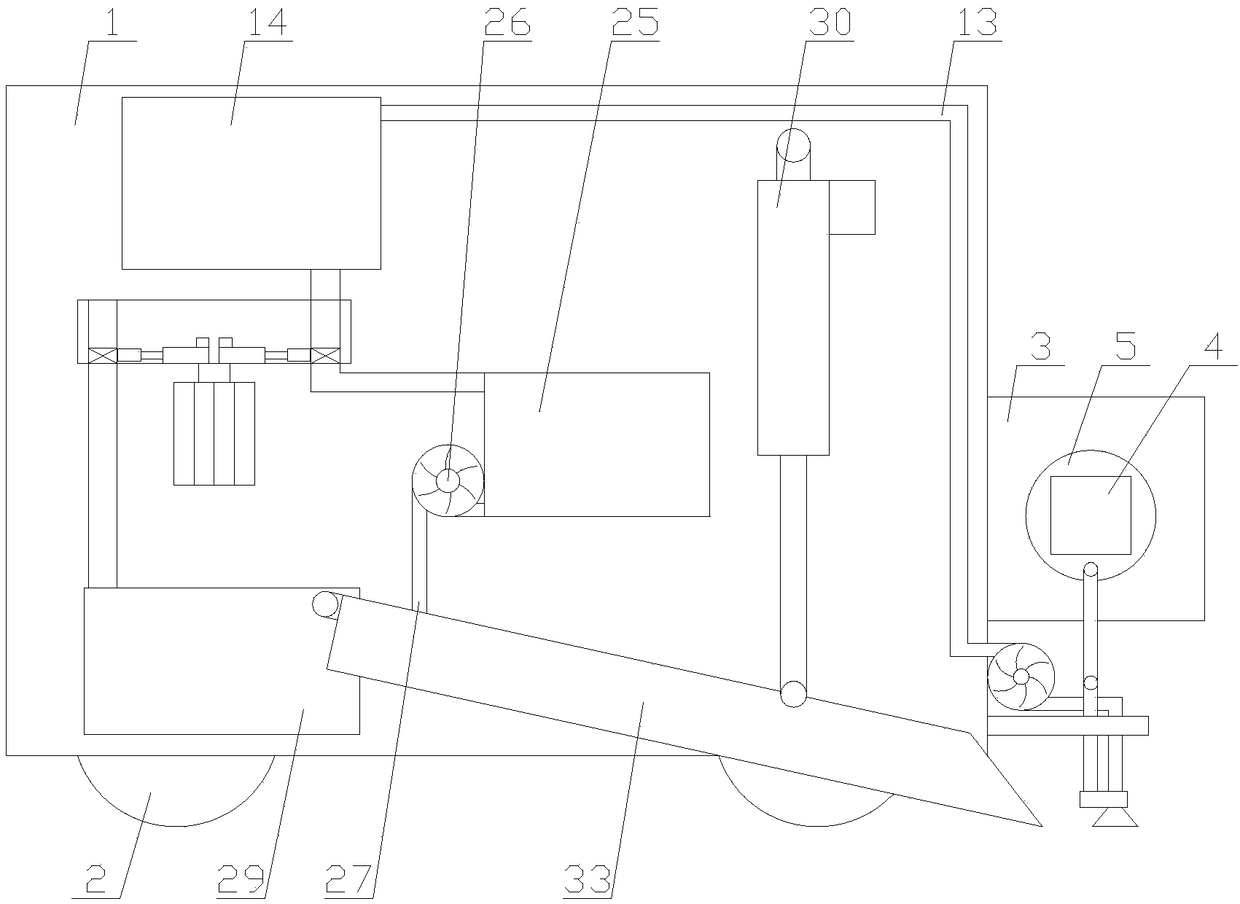
[0028] Such as figure 1 As shown, a smart utility gallery maintenance equipment with dewatering and dredging functions includes a casing 1, a support block 3, a pumping mechanism, a mud storage box 29, two dredging mechanisms, and four wheels 2, four wheels 2 They are all arranged in the casing 1, and the four wheels 2 are respectively arranged at the four corners of the casing 1, the support block 3 is fixedly connected with the casing 1, the mud storage box 29 is arranged at the bottom of the casing 1, and two dredging mechanisms Both are arranged in the casing 1, and two dredging mechanisms are arranged on both sides of the mud storage box 29 respectively;...


PUM


Abstract

The invention relates to an intelligent pipeline corridor maintenance device with water removing and dredging functions. The intelligent pipeline corridor maintenance device comprises a shell, a supporting block, a water pumping mechanism, a mud storage box, two dredging mechanisms and four wheels, the water pumping mechanism comprises a water suction unit, a sewage box and a filtering unit, the water suction unit comprises a first motor, a turntable, a swing rod, a moving rod, a lifting block, a limit rod, a water suction cover, a water suction pipe, a water pump and a water outlet pipe, andthe dredging mechanisms comprise second air pumps, second cylinders, second pistons and scraping plates. The intelligent pipeline corridor maintenance device is provided with the dredging mechanisms,so that sludge on the ground of a pipeline corridor can be cleaned, sludge in a drainage ditch can be cleaned, the drainage ditch is not plugged by the sludge, and the drainage capacity of the intelligent pipeline corridor is enhanced. Besides, the device is provided with the water pumping mechanism, the intelligent pipeline corridor maintenance device can remove water accumulated in the drainageditch of the pipeline corridor and can also remove water accumulated on the ground of the pipeline corridor, and rusting of pipelines and devices in the intelligent pipeline corridor is avoided.

Description

technical field [0001] The invention relates to the field of smart utility tunnels, in particular to maintenance equipment for smart utility tunnels with functions of water removal and desilting. Background technique [0002] Smart pipe gallery is a comprehensive corridor of underground urban pipelines, that is, to build a tunnel space underground in the city, integrating various engineering pipelines such as power, communication, gas, heating, water supply and drainage, etc., with special inspection ports and hoisting ports And monitoring system, the implementation of unified planning, unified design, unified construction and management, is an important infrastructure to ensure the operation of the city, and the maintenance equipment of smart pipe gallery is an important equipment to maintain the normal operation of smart pipe gallery. [0003] The inside of the pipe gallery should be kept dry and clean. When there is water and silt, the pipe gallery needs to be pumped and ...

Claims


Application Information

Patent Timeline
Patent Type & Authority Applications(China)
IPC IPC(8): E02F5/28E02F3/88E02F3/90E02F3/92E03F7/10
CPCE02F5/285E02F3/8816E02F3/90E02F3/92E02F3/9243E03F7/103E03F7/106
Inventor 陈德宏
Owner NANJING AITASI INTELLIGENT TECH CO LTD
Why Eureka
Try Eureka