an isolation mechanism

A technology of isolating mechanism and rotating motor, applied in the testing of machine/structural components, mechanical equipment, machine/engine, etc., can solve the problem of large change in driving force, difficulty in realizing the action performance of the gunpowder pin puller, and inability to realize the reverse rotation of the rotating wheel. Turn drive and other problems to achieve the effect of improving reliability

Active Publication Date: 2020-01-31
GUIZHOU AEROSPACE ELECTRONICS TECH CO LTD
View PDF5 Cites 0 Cited by
  • Summary
  • Abstract
  • Description
  • Claims
  • Application Information

AI Technical Summary

Problems solved by technology

[0004] 1. The driving force of the isolation mechanism in the traditional design is a torsion spring or a compression spring, which cannot realize the reverse driving of the rotating wheel, and it is not convenient for the wheel to return to the initial state after the release of the secondary insurance, and the driving force is relatively large in the initial stage. Small, the driving force changes greatly, the rotating wheel of the isolation mechanism may not rotate properly, and the reliability is low;
[0005] 2. The constraint of the traditional isolation mechanism is the constraint of the fire pin puller;
[0006] 3. The traditional isolation mechanism uses a gunpowder pin puller to restrain the gunpowder pin puller. The gunpowder pin puller is a one-time use device. When testing the release performance of the secondary insurance, only the destructive test can be performed on the gunpowder pin puller. It is difficult to detect the action performance of the powder pin puller of the isolation mechanism during the test, so there are certain deficiencies in the usual test

Method used


Image

  • an isolation mechanism
  • an isolation mechanism

Examples


Embodiment Construction

[0022] The technical solution of the present invention is further described below, but the scope of protection is not limited to the description.

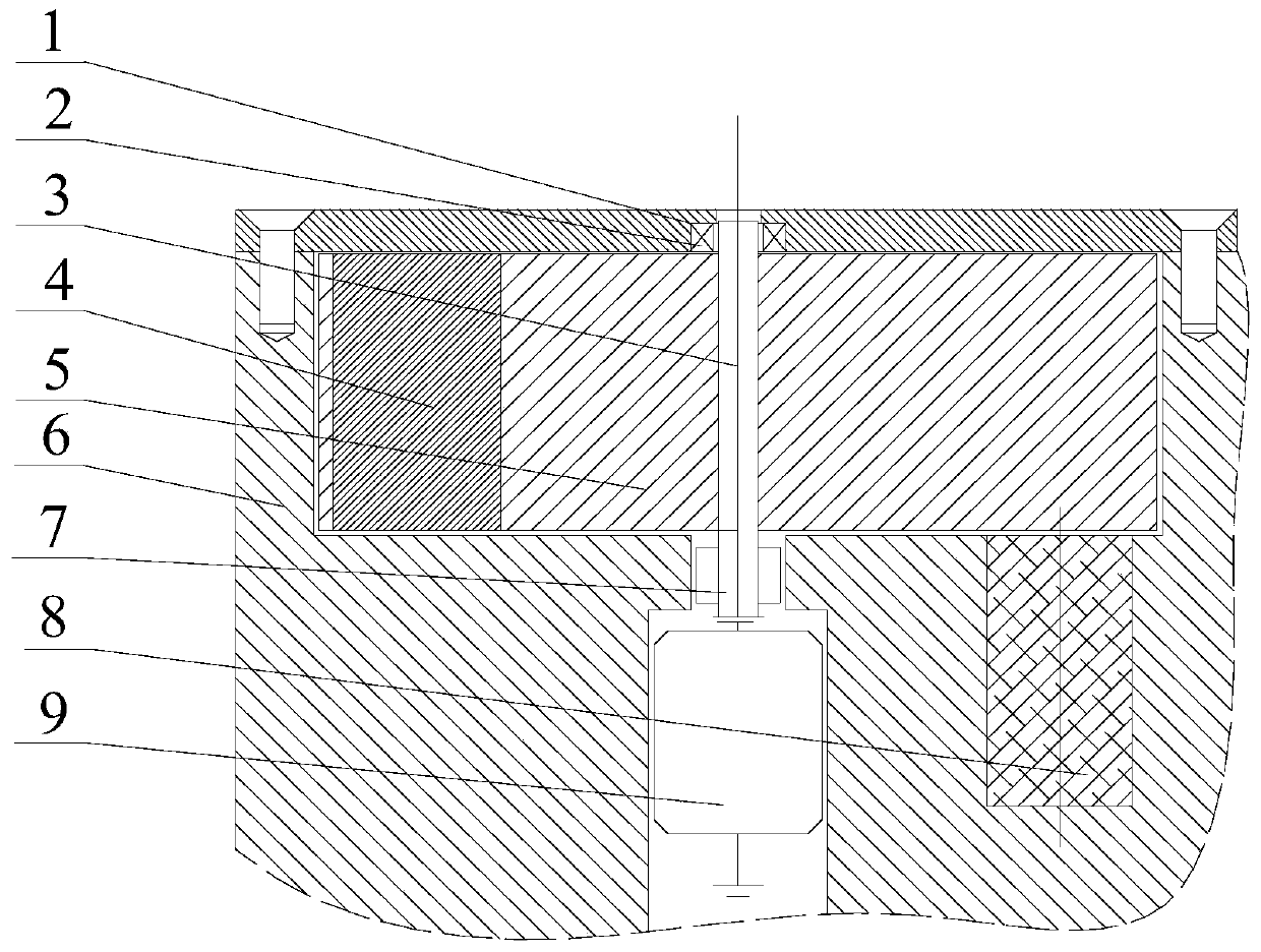
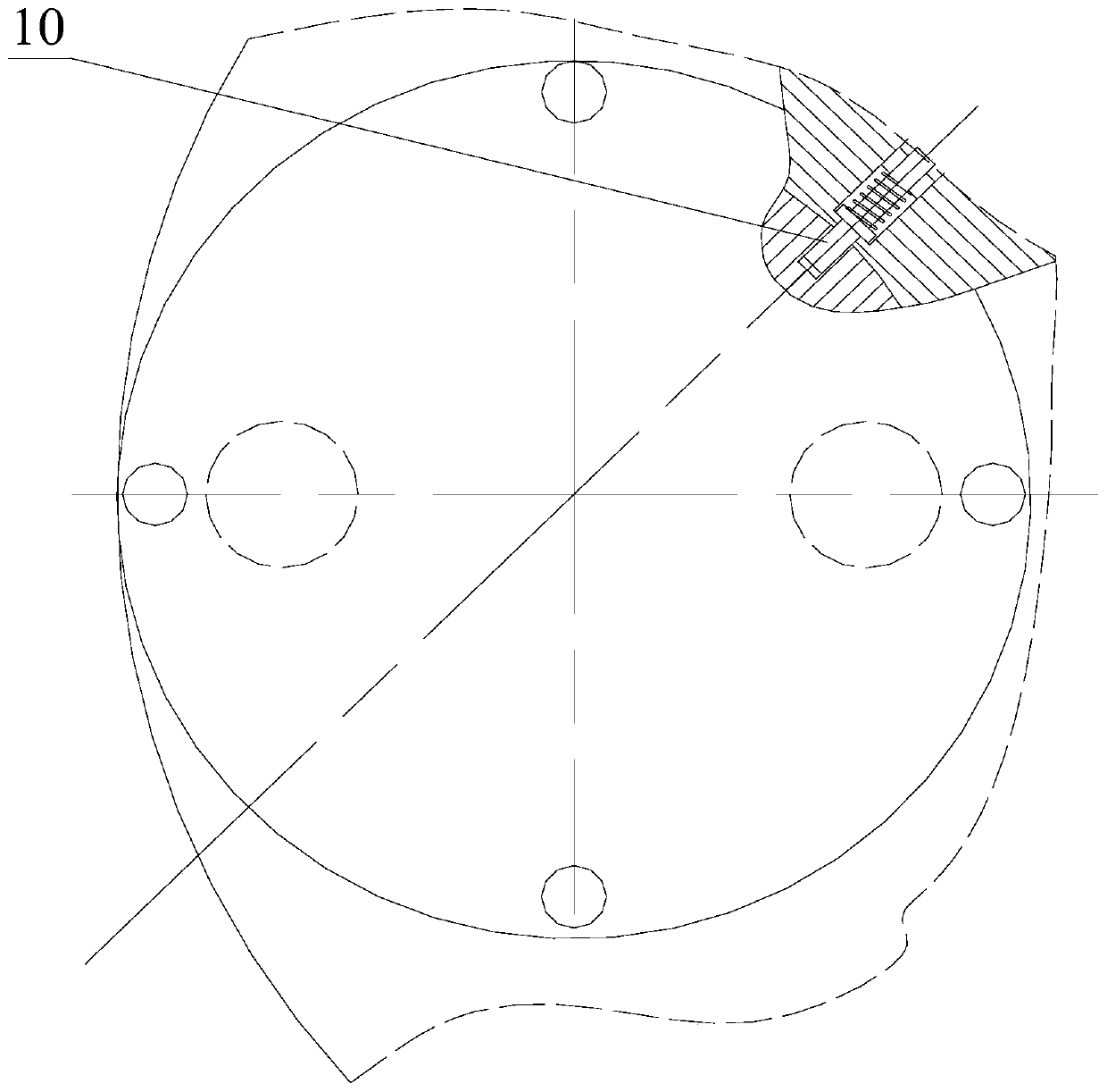
[0023] Such as figure 1 , figure 2 The shown isolation mechanism includes a rotating shaft 3, a powder column 4, a rotating wheel 5, a mounting seat 6, an action source 8, and a rotating motor 9; the mounting seat 6 has a cylindrical cavity, and the rotating shaft 3 is fixed vertically and coaxially In the cavity, a rotating wheel 5 is fixed on the rotating shaft 3, a rotating motor 9 is fixed at the bottom of the rotating shaft 3, and the rotating motor 9 drives the rotating shaft 3 to rotate; the inner edge of the rotating wheel 5 is fixed with a drug column 4 and a mounting seat 6 The action source 8 is set at the position below the corresponding powder column 4 inside.

[0024] An electromagnetic clamp 7 is sleeved and fixed on the rotating shaft 3 between the rotating wheel 5 and the rotating motor 9 .

[0025] An openable...


PUM


Abstract

The invention provides an isolation mechanism. The isolation mechanism comprises a rotary shaft, grain, a rotary wheel, an installing seat, an action source and a rotary motor, wherein a cylindrical cavity is formed in the installing seat; the rotary shaft is vertically and coaxially fixed in the cavity and fixedly provided with the rotary wheel; the rotary motor is fixed at the bottom end of therotary shaft and drives the rotary shaft to rotate; the grain is fixed to the position, near the edge, inside the rotary wheel in a penetrating mode; and the action source is arranged at the position,corresponding to the lower portion of the grain, in the installing seat. The rotary motor provides driving force, reverse rotation driving of the rotary wheel is realized, the isolation mechanism ofa device can conveniently restore to the initial state after two-level safety is relieved, the driving force on the rotary wheel at the initial stage and the ending stage is uniform, the rotary wheelis effectively driven to rotate in place, and the reliability of relief of two-level safety is improved. An electromagnetic clamp device is used for conducting two-level safety restraining on the isolation mechanism, and the relief performance of two-level safety of the isolation mechanism can be detected without carrying out a destructive test.

Description

technical field [0001] The present invention relates to an isolation mechanism. Background technique [0002] The action execution part is an important part of the aircraft. Its function is to receive the start signal to start the corresponding parts of the aircraft. It is widely used in aerospace products. The inertial safety mechanism and isolation mechanism are the core of the action execution part. , transportation, and service processing are in the insurance state, before launching and entering the action zone, they are in the insurance state, and the first-level insurance release and the second-level insurance release are not allowed accidentally. After receiving the first-level insurance release signal and the second-level insurance release signal, successively When the first-level safety is released and the second-level safety is released, the device is in the waiting state, and it can reliably operate after receiving the start signal from the moving parts or other p...

Claims


Application Information

Patent Timeline
Patent Type & Authority Patents(China)
IPC IPC(8): F02K9/38G01M13/00
CPCF02K9/38G01M13/00
Inventor 石云陆
Owner GUIZHOU AEROSPACE ELECTRONICS TECH CO LTD
Why Eureka
Try Eureka